Example 6.2
Estimation of the design bearing capacity of a single pile according to AS2159 using the α- and β-Methods - Multilayered soil profile case
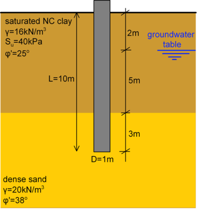
Determine the design bearing capacity of the concrete pile shown below, according to AS2159 provisions, using the simplified α– and β-Methods. For the specific problem, assume a basic geotechnical strength reduction factor φgb equal to φgb = 0.52. Ignore the weight of the pile.
Answer:
Since the problem is asking us to find the design bearing capacity, we will consider that the pile is loaded with axial compressive load. The design bearing capacity of the pile must be determined both under short-term and long-term loading conditions, in order to establish the critical design bearing capacity. The top clay layer will behave as undrained under short-term loading, and as drained under long-term loading. On the other hand, the bottom dense sand layer will behave as drained under both long-term and short-term loading.
- Estimation of the ultimate geotechnical strength under short-term conditions
1.1 Estimation of the skin friction resistance, Qsf:
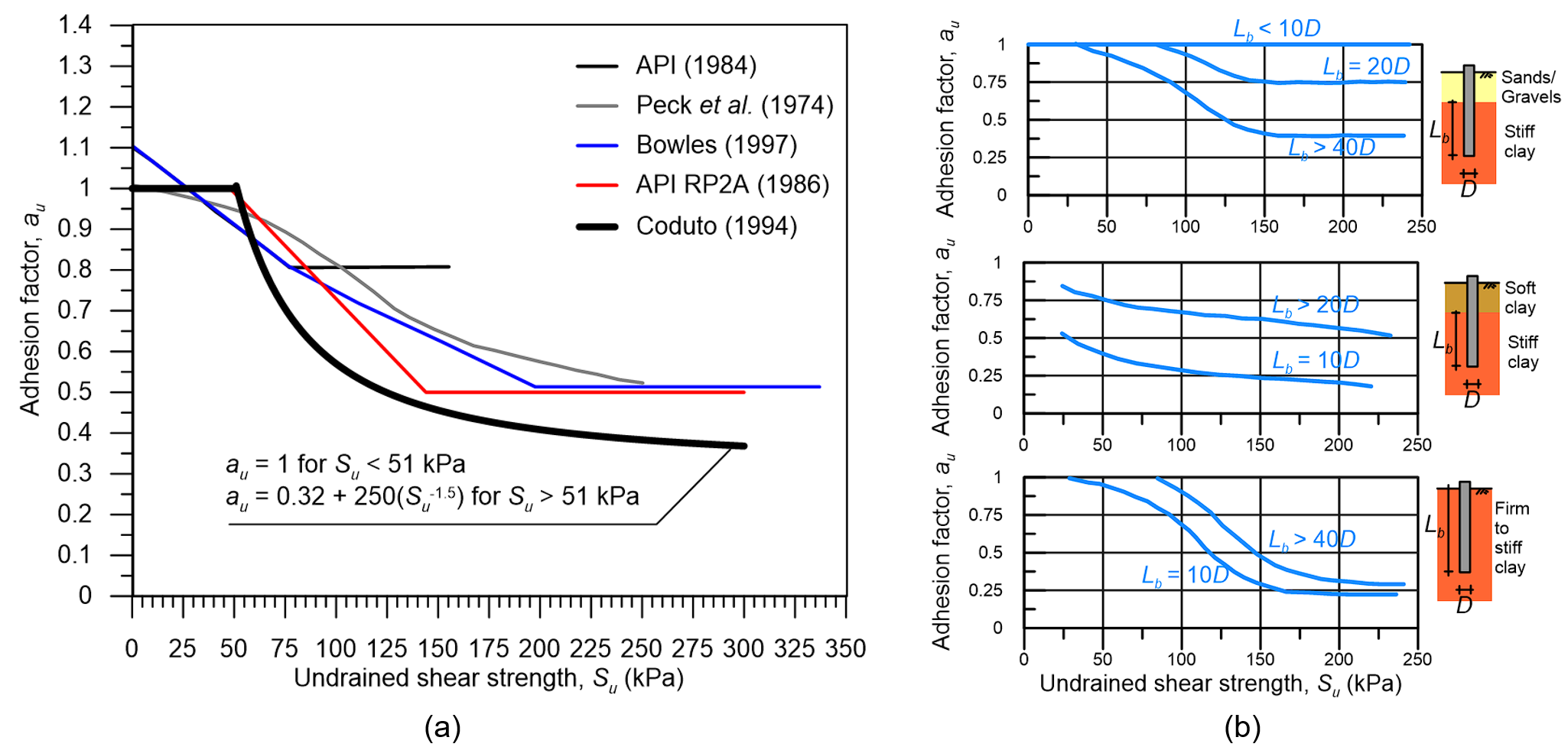
Clay layer (α-Method): According to Coduto (1994) (Figure 6.18a) for a uniform clay with Su = 40 kPa it is au = 1.00. Moreover, following AS 2159, the first 1.5D meters of the pile shaft will not contribute to the friction resistance of the part of the pile embedded in the clay layer (Eq. 6.6):

Dense sand layer (β-Method): First, we have to calculate the vertical effective stress at the middle (z = 8.5 m) of the sand layer σ′z0:

In order to find the β factor, we estimate the earth pressure coefficient at-rest Κ0 as (Eq. 6.16):

and the interface friction angle φi, which for a concrete pile with rough surface will be equal to 2/3 of the friction angle of the sand layer φ′ (Eq. 6.15):

Given the above, the β factor is calculated as (Eqs. 6.12-6.13):

and the skin friction resistance in terms of force of the part of the pile embedded in the dense sand layer will be equal to (Eq. 6.11):

It is interesting to note that the skin friction resistance in terms of stress fsf at the middle of the sand layer is fsf = 13.93 kPa. Considering the recommended values in Table 6.4, this is quite low, especially if we consider that the skin friction resistance in the overlying clay layer is fsf = 40 kPa. However, observe that we have used the in situ lateral earth pressure in the calculations from Eq. 6.16. Had we followed API RP2A recommendations and considered K = 0.8 to 1 to account for installation effects, we would have calculated fsf = Κtanφiσ′z0 = 1.0×0.473×77 = 36 kPa, which is considerably higher. This is an example where simplified methods, not accounting for installation effects, can provide over-conservative predictions.
1.2 Estimation of the end bearing resistance, Qb
The pile toe is embedded in the dense sand layer, thus we will use Eq. 6.19 for drained loading conditions. First, we have to estimate the vertical effective stress at the pile toe level (z = 10m) σ′z0,b:

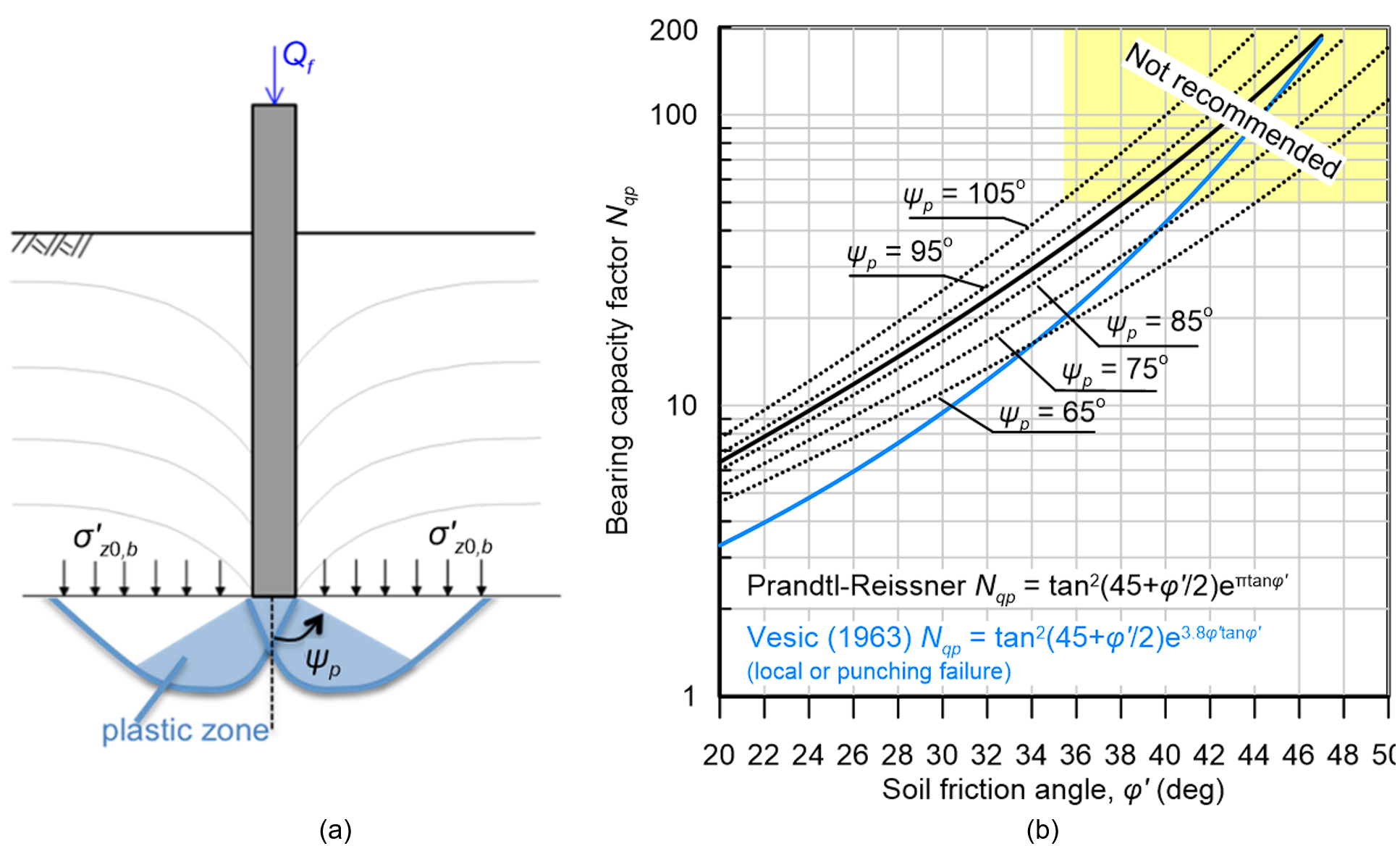
For the estimation of the bearing capacity factor Nqp we will use Eq. 6.19:

The calculated Nqp value is quite high, still within the recommended zone of Figure 6.21. The end bearing resistance is calculated as:

Note that if we use the expression recommended by Janbu (Eq. 6.20) to estimate the bearing capacity factor while considering a rational range of ψp values ψp = 75º to 85º we calculate bearing capacity factors ranging between Nqp ≈ 32 to 42 and the corresponding end-bearing resistance will be Qb ≈ 2312 to 3034 kN. These values are compatible with the recommended Nqp values in Table 6.4.
1.3 Ultimate geotechnical strength (collapse load) under short-term conditions
The collapse load is the sum of the pile’s skin friction resistance along the clay and the sand layer, and its end bearing resistance:

Notice that the over-conservative prediction of Qsf,sand had little effect on the collapse load (about 5%), which is governed by the end bearing resistance of the pile’s toe in sand.
2. Estimation of the ultimate geotechnical strength under long-term conditions
2.1 Estimation of the skin friction resistance, Qsf:
Clay layer (β-Method): We can divide the clay layer into two sublayers; one with thickness 2 m above the ground water table, and one with thickness 5 m below the groundwater table.
For the first sublayer (above the groundwater table):
vertical effective stress at the middle (z = 1.0 m) of sublayer 1 σ′z0,1:

lateral earth pressure coefficient (Eq. 6.15):

Interface friction angle φi for a rough concrete pile (Eq. 6.15):

β factor (Eqs. 6.12-6.13):

For the second sublayer (below the groundwater table):
vertical effective stress at the middle (z = 4.5 m) of sublayer 2 σ′z0,2:

and 
Using Eq. 6.14, the total skin friction resistance of the clay layer will be:

Note that if we considered the clay layer as a single layer, and calculated the vertical effective stress at its middle (z = 3.5 m), we would calculate a total skin friction resistance Qsf,clay = 122 kN.
If we assume the same ICP parameters for clay as in Example 6.1 (St = 1, φi = 25 deg) we would calculate according to the ICP method at the middle of the clay layer:

![{\sigma '_{he}} = {K_c}{\sigma '_{z0}} = 26\left[ {2.216} \right]{1.0^{0.42}}{\left[ {13} \right]^{ - 0.20}} = 34.5{\rm{ \:kPa}}](https://oercollective.caul.edu.au/app/uploads/quicklatex/quicklatex.com-6cacaabb5db496950866a2e7a07db8cb_l3.png "Rendered by QuickLaTeX.com")


Therefore, unlike Example 6.1., here the ICP method provides considerably higher skin friction resistance for the clay layer, noting though that the ICP method is based on ESA concepts, and does not differentiate between long-term and short-term skin friction resistance.
As far as the skin friction resistance of the part of the pile embedded into the sand layer, it will be essentially the same as under short-term conditions:

2.2 Estimation of the end-bearing resistance, Qb:
The same applies for the end-bearing resistance of the pile toe embedded in sand: it will be the same as under short-term conditions:

2.3 Ultimate geotechnical strength (collapse load) under long-term conditions, Qf:
The collapse load is the sum of the long-term pile’s skin friction resistance along the clay and the sand layer, and its end-bearing resistance:

3. Estimation of the design bearing capacity, φgbQf:
It appears that in this case, the long-term loading is critical, as it results in the lowest pile ultimate bearing capacity. The design bearing capacity according to AS2159 is calculated as:

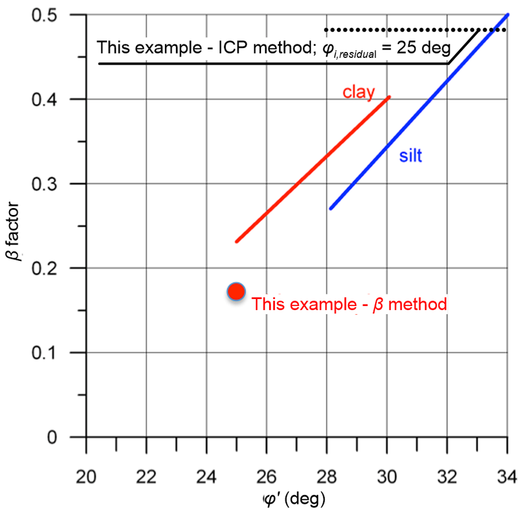
This is due to the long-term skin friction resistance in the clay layer being lower that the short-term skin friction resistance, and appears to be counterintuitive: As discussed in Part 5, we would expect the short term loading to be critical. However, comparisons with the ICP method have demonstrated that the α-method appears to be overestimating the skin friction resistance for soft-to-firm clays, and at the same time the β-method appears to be underestimating the skin friction resistance. Indeed, pile test results (Fellenius 1991) indicate that for clays and silts, the factor β usually ranges between 0.25 and 0.40 depending on their friction angle, as shown in Figure 6.44. In this example we have calculated β = 0.172 for the clay layer with φ′ = 25 deg, while the ICP method provides β = fsf/σ′z0 = 12.86/26 = 0.49.

