Example 6.11
Numerical simulation of negative skin friction effects: estimation of the elevation of the neutral plane for different applied load levels
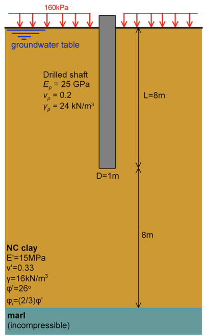
After construction of the drilled shaft of the figure, the area around the shaft is backfilled, and a uniform surcharge of magnitude 160 kPa is applied on the ground surface. Assuming for simplicity that the total settlement is equal to the immediate settlement, determine the location of the neutral plane:
- Before any load is applied on the shaft,
- If a vertical load equal to about 10% of the long-term collapse load is applied on the pile, and
- If the pile is loaded up to its long-term collapse, defined as the load resulting to shaft head displacement uy,f equal to 0.3D.
Answer:
This simplified problem is used to “visualise” the concept of the negative skin friction and of the neutral plane, described in Chapter 6.22, and follows the same general concepts of numerical simulation of piles subjected to vertical loads developed in Examples 6.3 and 6.4. Note that in practice negative skin friction effects on piles is a three-dimensional problem, as an approach embankment will not apply a uniform surcharge on the surface of the soil surrounding the pile. Nevertheless, we consider a simplified axisymmetric version of the problem here, as the aim of this example is to demonstrate to the reader how the elevation of the neutral plane changes as the axial load applied on the pile head increases.
The response of the clay will be simulated as drained, employing the Drained Mohr-Coulomb model, as we assume that excess pore pressures will have dissipated, and settlement due to the application of the surcharge will have been completed, before any load is applied on the shaft. Although the cohesion of the normally consolidated clay is assumed equal to zero (c′ = 0), a small value of cohesion (c′ = 1 kPa) is considered with the Drained Mohr-Coulomb model, for numerical stability reasons. A linear-elastic material is used to simulate the shaft, with Young’s modulus Ep = 25 GPa and Poisson’s ratio vp = 0.2. The interface strength reduction factor Rint for a concrete drilled shaft under long-term load conditions is defined as:

where φ′ = 26º.
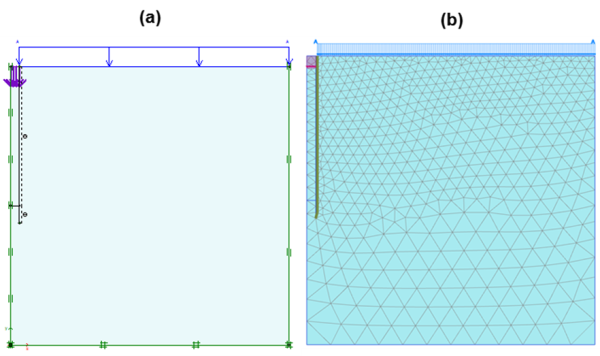
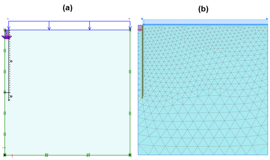
The considered model geometry and the finite element mesh are presented in Figure 6.85.
The analysis is performed in 4 stages:
- Initial stage (before the construction of the shaft) Calculate initial geostatic stresses with the “K0 procedure”, while associating all geometry clusters with the original soil material.
- Plastic stage 1 (construction of the shaft) The material of the geometry cluster corresponding to the shaft is switched to the linear elastic material described above, and interfaces are activated.
- Plastic stage 2 (application of the surcharge) A uniform pressure of q = 160 kPa is applied on the top of the mesh, but not on the shaft head.
- Plastic stage 2 (loading of the shaft) An imposed displacement of maximum magnitude 0.3D = 0.3m is applied at the head of the shaft. Results during intermediate analysis stages are saved too.
Note that, as an effective stress analysis is performed, the groundwater table level must be explicitly introduced during the definition of the analyses stages.
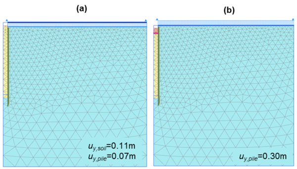
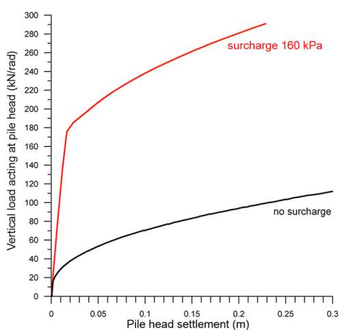
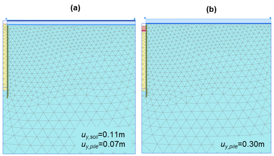
Snapshots of the deformed mesh are presented in Figure 6.86, after the application of the surcharge, and after loading the shaft up to failure. As expected, application of the surcharge results to some settlement of the shaft, although no load is applied on its head (see also Figure 6.87a). On the contrary, as the shaft is loaded up to its collapse load, its head settles more than the surrounding soil.
The location of the neutral plane can be found by plotting the shear stress along the soil-pile interface, as illustrated in Figure 6.87b. The neutral point is located initially, when zero load is applied at the pile head, at a depth equal to 0.75L from the head, quite close to the theoretical value of 0.66L which applies for linearly increasing shear strength of clay with depth (as it will be the case for drained loading). As a vertical load is applied on the shaft head, the neutral plane moves upwards, and negative skin friction stresses are reduced. When the collapse load is reached, as expected, negative stresses at the interface vanish, the neutral plane is now located at the pile head, and the full length of the shaft contributes to the resistance by developing positive skin friction. This demonstrates that negative skin friction is a settlement, rather than a resistance problem.
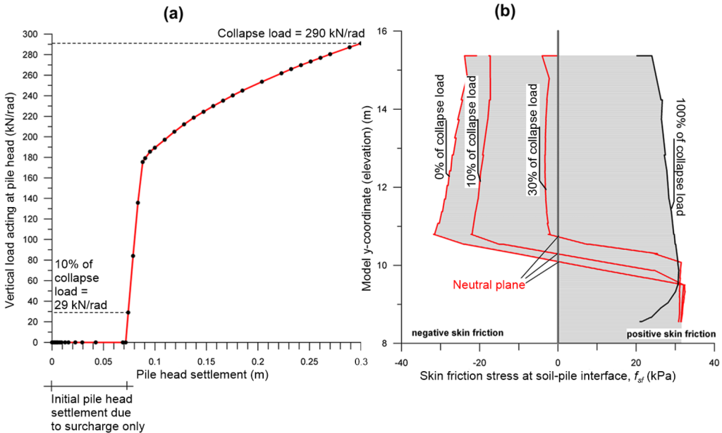
Further to that, it is interesting to compare the load-settlement curve of Figure 6.87a with the load-settlement curve that would result from an additional analysis, without applying a surcharge load (Figure 6.88). Clearly, the surcharge has a beneficial effect on the bearing capacity of the shaft, as it results in increased vertical, and consequently lateral effective stresses along the shaft length, thus in increased skin friction resistance (Eq. 6.12-6.13).
