Example 4.8
The importance of boundary conditions
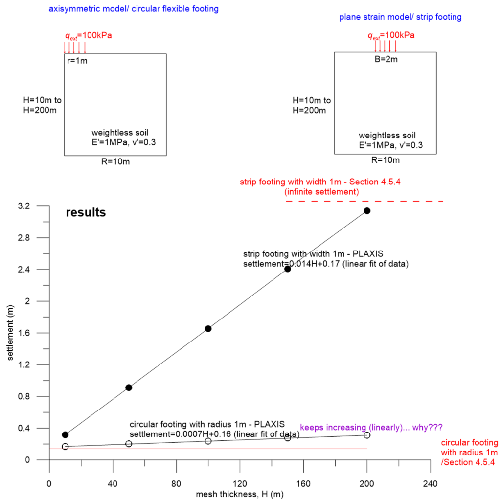
In this example we employ PLAXIS to validate the results of the simple, approximate method described in Section 4.5.4 for calculating immediate settlements of footings on linear elastic half-space. For that we will built two PLAXIS models, shown in Figure 4.54: A plane-strain one simulating a strip footing and an axisymmetric one simulating a circular footing.
Keep in mind that the method described in Section 4.5.4 does not work for strip footings, as it predicts that infinite settlement will occur (see Table 4.3). To confirm that, we start by building a model in PLAXIS with initial thickness 10 m, and run 5 simulations in total while increasing the thickness of the mesh from H = 10 m to H = 50 m, H = 100 m, H = 150 m and finally H = 200 m. Indeed, it appears that the more we increase H, the larger the settlement (settlements increase linearly) and settlement tends to infinity for an infinitely thick mesh.
However, results for a circular footing are rather puzzling. The analytical method yields an immediate settlement of 140 mm for the problem herein. Then we model the same problem in PLAXIS, starting with mesh thickness 10 m as shown in Figure 4.54, and again run multiple simulations while increasing H as above. Results of the first analysis for H = 10 m are relatively close to the analytical solution, as settlement from PLAXIS is about 170 mm. Keeping in mind that the solution is “approximate”, a 30 mm difference is acceptable, especially if we consider that the analytical method is applicable to rigid footings and in PLAXIS we are modelling an infinitely flexible footing by means of a pressure applied at the surface of the model. But as we keep increasing H again to 200 m, settlement yet again increases linearly instead of reaching an asymptote, as expected. The gradient is not as steep as in the strip footing case (notice the linear fit of the numerical data), but at H = 200 m the PLAXIS settlement is already twice the analytical one, and we infer that it will reach 1.5 m if H was H = 2000 m. That’s certainly not compatible with the analytical solution.
Is there a fundamental error in the analytical method, or there is an error in our numerical models?
Answer:
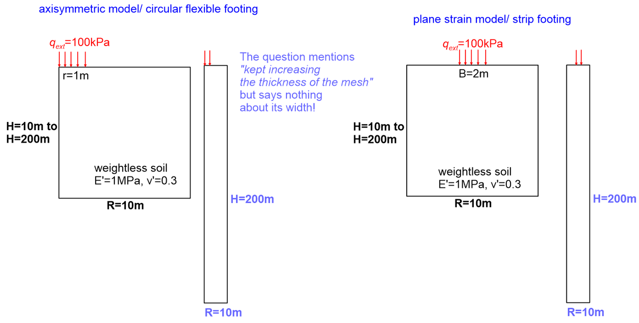
Indeed, results presented in Figure 4.54 are flawed, but the error lies in the numerical solution, and not in the analytical results. The question mentions that we increase the thickness of the mesh from 10 m to 200 m, but does not mention anything about changing proportionally the mesh width, as seen in Figure 4.55.
When standard fixities are used in a numerical model i.e., the horizontal displacement is fixed at the lateral boundaries, we set the particular boundary to be an axis of symmetry. Therefore a “mirror” loading acts at a horizontal distance e.g., 8 m from the strip footing in Figure 4.55 and contributes to settlement (see also additional Example 3.2).
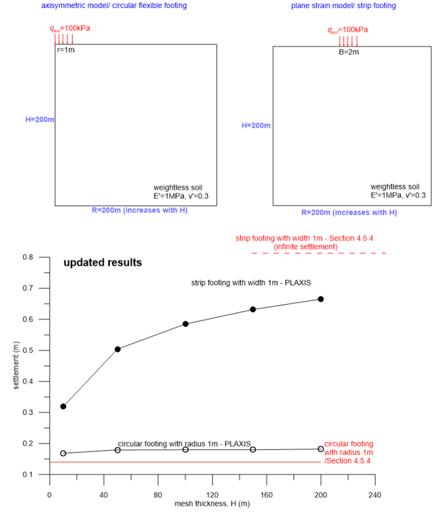
Correct (i.e. not compromised by boundary effects) results are depicted in Figure 4.56, and are obtained by increasing proportionally the mesh width to the mesh thickness. All other analysis parameters remain unchanged. Notice that indeed settlement of a strip footing increases indefinitely as the mesh thickness increases, as intuitively expected for a plane-strain pressure acting on the top of a half-space (when the out-of-plane displacement is fixed to satisfy symmetry).
However, this is not the case for the circular footing, where settlement reaches an asymptote before the mesh thickness increases more than 40 m. In fact, the analytical solution is quite close to the numerical solution, and the above results verify its validity.
This rather crude example stresses out the importance of model boundary conditions in getting realistic results, and the need to carefully investigate the sensitivity of the solution to the boundary conditions (instead of relying on rules-of-thumb), to ensure that it is not compromised by errors introduced in the modelling stage. Analytical methods, such as the one described in Section 4.5.4 are invaluable for obtaining at least a first estimate of the expected solution.

