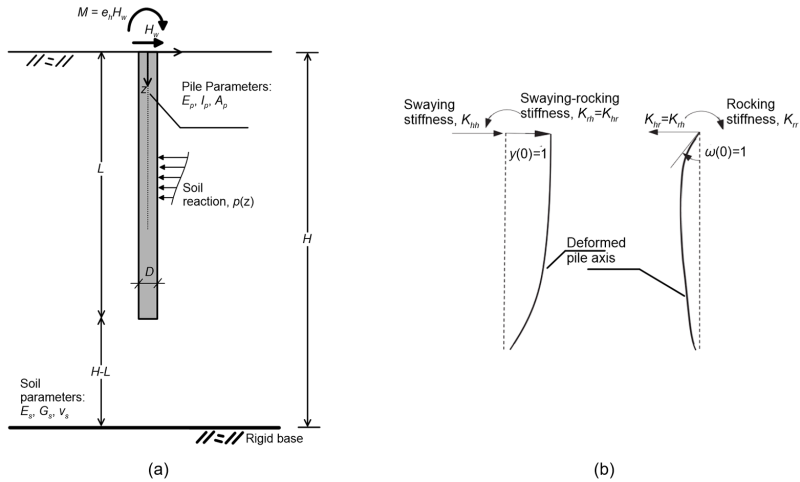
6.26 Rigorous elasticity method for estimating pile deformations
As previously mentioned, Brom’s method for estimating pile head deflection requires estimating the coefficient of subgrade reaction Kh by means of empirical formulas. As such, the method is inherently approximate. A rigorous method for estimating the deflection but also the rotation of the head of a single pile has recently been developed by Zheng et al. (2024). Their formulation is based on modelling soil as elastic Tajimi-type medium, and ignoring possible slippage or separation at the soil-pile interface, therefore is applicable mainly to serviceability conditions. Zheng et al.’s method allows estimating the swaying Khh, rocking Krr and swaying-rocking Krh = Khr components of the head stiffness of a single floating pile embedded in elastic soil of finite thickness (Figure 6.109a).
It is reminded that the swaying stiffness Khh is the lateral load Hw that, when applied to the head of a pile results in head deflection y(0) = 1 (Figure 6.109b). The rocking stiffness Krr is the bending moment Mw that, when applied to the head of a pile results in head rotation ω(0) = 1 (Figure 6.109b). The swaying-rocking stiffness Krh is the bending moment that will develop to a pile with fixed head rotation ω(0) = 0 when the pile is subjected to unit displacement at its head y(0) = 1, considering the sign convention in Figure 6.109b. The swaying-rocking stiffness Khr is the lateral force that will develop to a pile with fixed head displacement y(0) = 0 when the pile is subjected to unit rotation at its head ω(0) = 1, considering the sign convention in Figure 6.109b. Moreover, it is Krh = Khr.
Using Zheng et al.’s method to calculate the stiffness components allows establishing the stiffness [K] and compliance [S] matrixes of the pile, as:
(6.128a) ![\left[ {\begin{array}{*{20}{c}}{{H_w}}\\{{M_w}}\end{array}} \right] = \left[ {\bf{K}} \right]\left[ {\begin{array}{*{20}{c}}{y(0)}\\{\omega (0)}\end{array}} \right] = \left[ {\begin{array}{*{20}{c}}{{K_{hh}}}&{{K_{hr}}}\\{{K_{rh}}}&{{K_{rr}}}\end{array}} \right]\left[ {\begin{array}{*{20}{c}}{y(0)}\\{\omega (0)}\end{array}} \right]](https://oercollective.caul.edu.au/app/uploads/quicklatex/quicklatex.com-b2d3bdddcb83a46e0d1443c0a0ba41b8_l3.png "Rendered by QuickLaTeX.com")
(6.128b) ![\left[ {\begin{array}{*{20}{c}}{y(0)}\\{\omega (0)}\end{array}} \right] = \left[ {\bf{S}} \right]\left[ {\begin{array}{*{20}{c}}{{H_w}}\\{{M_w}}\end{array}} \right] = {\left[ {\bf{K}} \right]^{ - 1}}\left[ {\begin{array}{*{20}{c}}{{H_w}}\\{{M_w}}\end{array}} \right]](https://oercollective.caul.edu.au/app/uploads/quicklatex/quicklatex.com-edea58d3055a923b3dadd514e4d7e3e0_l3.png "Rendered by QuickLaTeX.com")
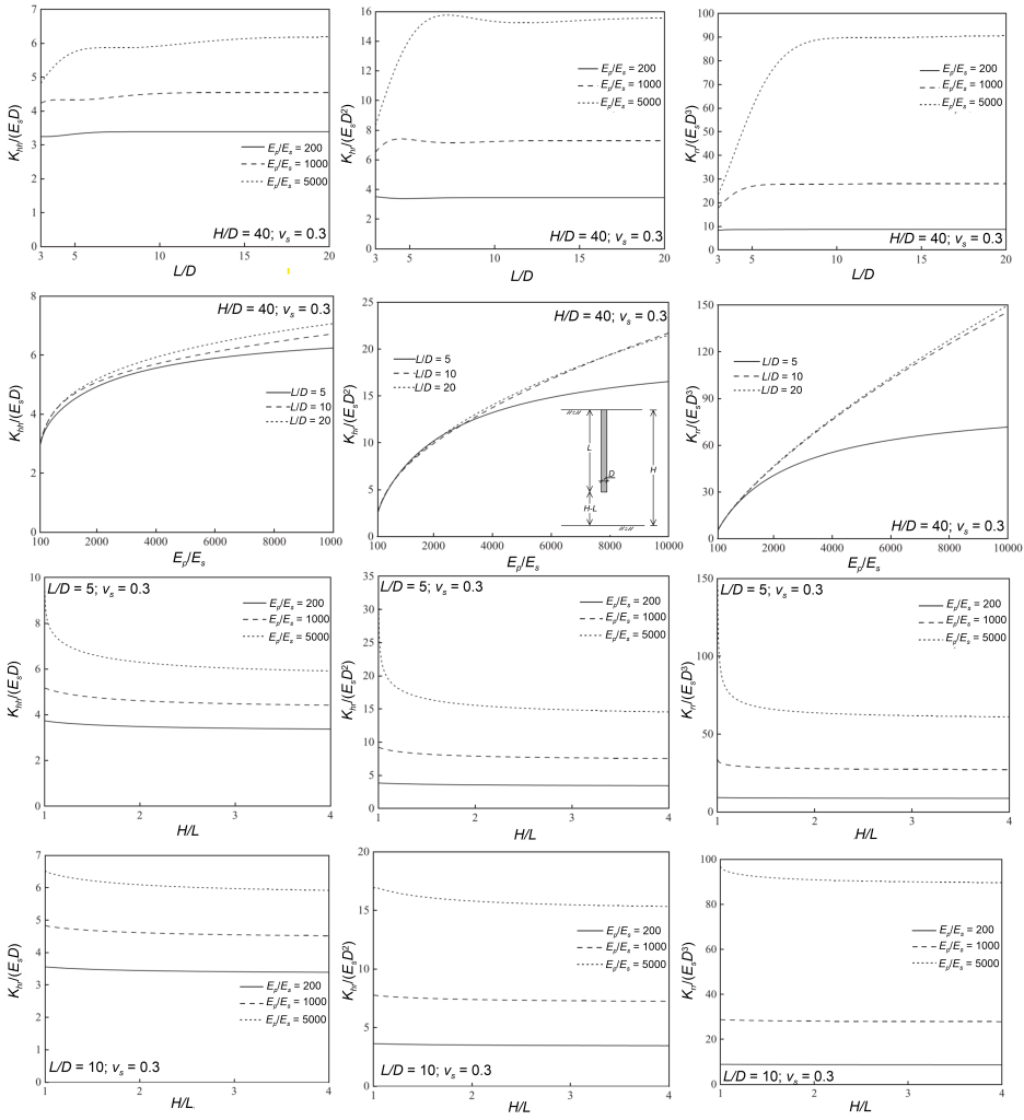
It is reminded that the stiffness and compliance matrixes are independent of the load conditions, and of any restrains imposed to pile head deflection or rotation. The charts provided in Figure 6.110 allow calculating directly the components of the stiffness matrix for soil with Poisson’s ratio vs = 0.3 and different values of the pile-soil moduli ratio Ep/Es, the slenderness of the pile L/D and the dimensionless thickness of the foundation soil layer H/L. Having estimated these components one can calculate the compliance matrix by inverting the stiffness matrix, and subsequently the deflection y(0) and the rotation ω(0) of the pile head for any load combination acting at the pile head, as well as head fixity conditions.
It is interesting to observe in Figure 6.110 that there exists a critical pile slenderness ratio L/D, beyond which pile stiffness becomes independent of the length of the pile, and the bottom part of the pile no longer contributes to its response to lateral load. Therefore one can argue that, if the top part of the soil profile of dimensionless thickness equal to the critical pile slenderness comprises uniform soil conditions, this method (but also Broms method) will provide reasonably accurate results, even when the pile is installed in layered soil. This is not limited to serviceability conditions, but can be extrapolated to the estimation of the collapse lateral load. However, the critical pile slenderness is not the same for all components of stiffness, and on top of that it varies with the pile-soil moduli ratio Ep/Es.
