6.25 Broms method – Piles in drained soil
6.25.1 Short free-head piles
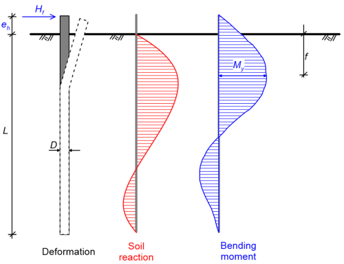
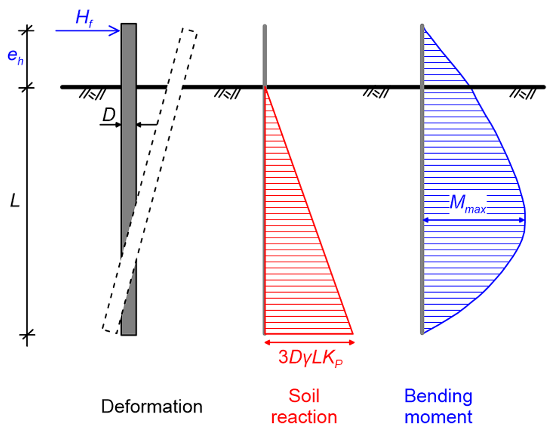
As in the case of piles in undrained soil, determination of the ultimate geotechnical strength and of the maximum bending moment developing on piles under drained loading conditions is based on static equilibrium considerations (Figure 6.102), while accounting for the rotation boundary conditions at the pile head. The ultimate soil reaction, developing at the pile toe, is calculated while assuming that the earth pressure acting on the pile is equal to three times the Rankine passive pressure. Further assuming that the ultimate soil reaction decreases linearly to zero at the ground surface, the ultimate soil reaction pf per unit pile length at a depth z below the soil surface (units: force/length) is calculated as:
(6.116) 
Where:
(6.117) 
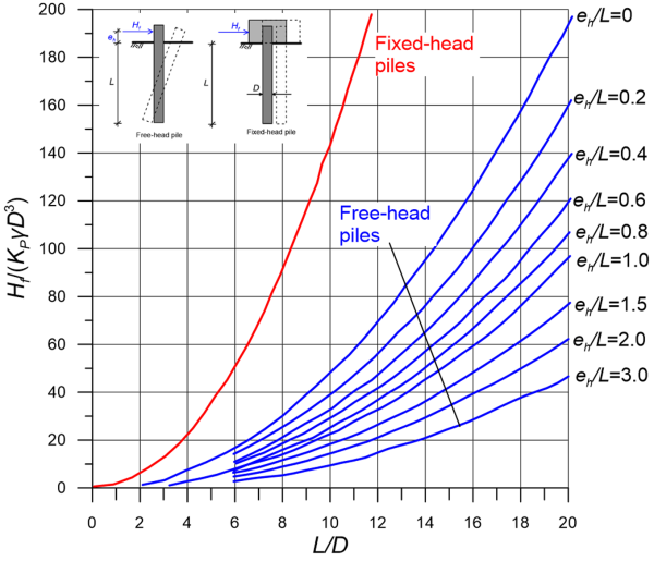
is Rankine’s passive earth pressure coefficient, γ is the unit weight of the soil, and φ′ is its friction angle. Accordingly, the collapse lateral load Hf can be either determined from Figure 6.103, or directly as:
(6.118) 
Given the collapse lateral load Hf, the maximum bending moment that will develop on the pile Mmax is calculated as:
(6.119) 
where f (units: length) defines the location where the maximum bending moment will develop along the pile:
(6.120) 
The above formulas must be used together with the submerged unit weight of the soil, if the groundwater table level is relatively high.

6.25.2 Short fixed-head piles
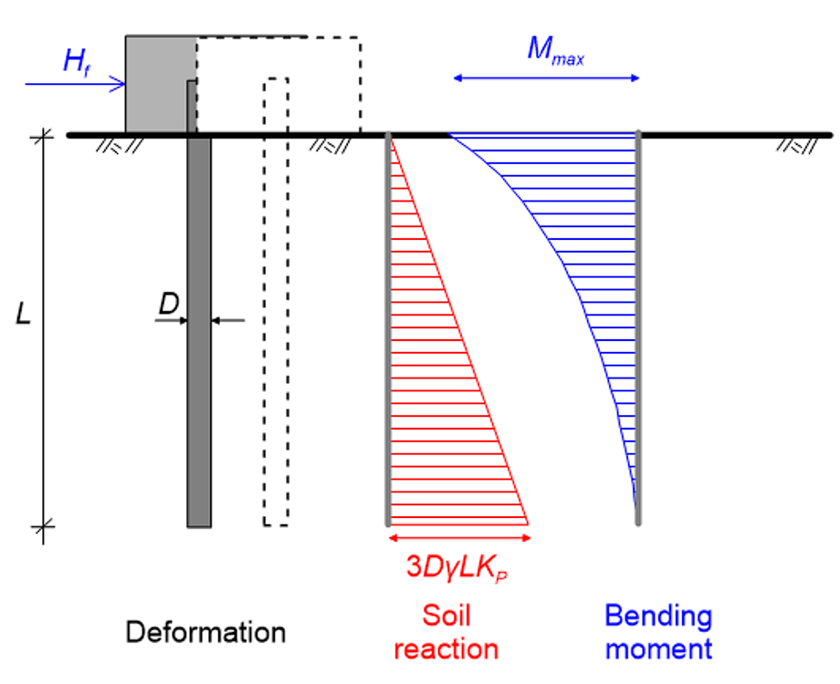
The same procedure is followed for fixed-head piles too, that translate as a rigid body, assuming again that the ultimate lateral reaction pf develops at the pile toe and is calculated while assuming that the earth pressure acting on the pile equal to three times the Rankine passive pressure (Figure 6.104).
The collapse lateral load Hf can be either found using Figure 6.103, or directly via static equilibrium considerations as:
(6.121) 
The maximum bending moment Mmax that will develop at the head of pile, at the connection with the rigid cap, is estimated with the following Eq. 6.122, using again the submerged unit weight of the soil, if applicable:
(6.122) 

6.25.3 Long free-head piles
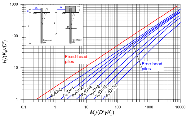
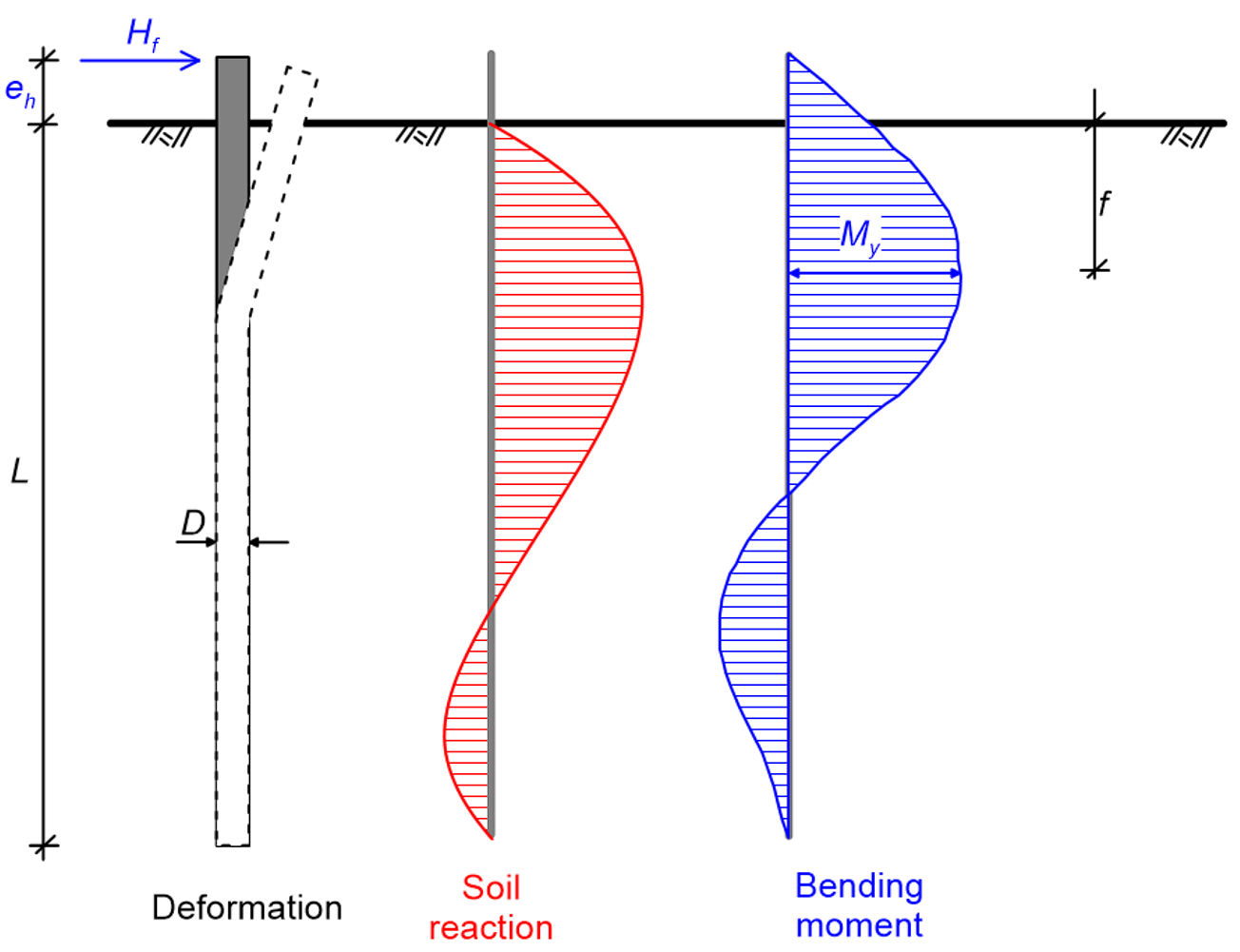
As in the case of long piles driven through undrained soil, the ultimate soil reaction that can theoretically develop along the pile length is very high. Therefore, before the ultimate soil reaction is mobilised along the entire pile length, a plastic hinge will develop at depth f given by Eq. 6.120 where the maximum bending moment becomes equal to the yield moment of the pile’s section, My (Figure 6.105). The collapse lateral load, Hf is determined from Figure 6.106, or directly as:
(6.123) 
As in the case of piles in undrained soil, both the short pile and the long pile failure modes must be considered, to find the critical, minimum collapse load that the pile can carry. To determine whether the pile will fail as a short pile or as a long pile first, one should start again with the expressions in Section 6.25.1 for a short pile. If the resulting maximum bending moment is larger than the yield moment, the formulas for long pile failure must be used, as they will yield lower collapse lateral load.
6.25.4 Long fixed-head piles
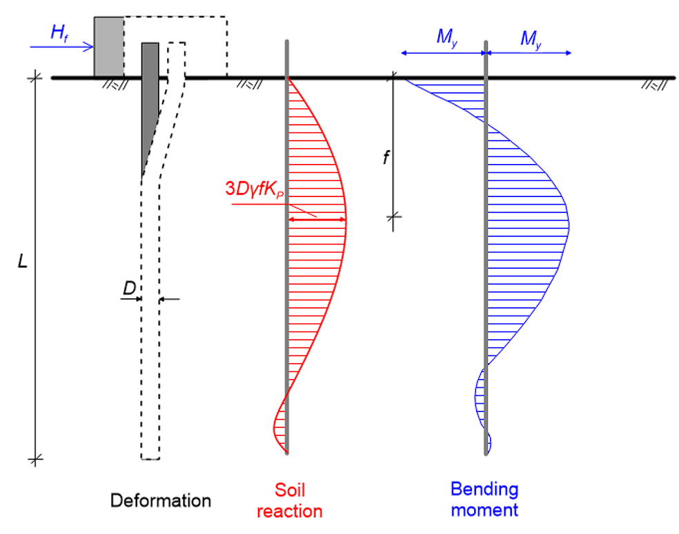
As for long free-head piles, the plastic (yield) bending moment, My will be reached before the ultimate soil reaction is mobilised along the full length of the pile. Similarly to the case of a pile driven through undrained soil, failure will occur with the formation of two plastic hinges (Figure 6.107): one at the connection of the pile with the cap, where the pile is fixed against rotation, and a second at the point where the maximum bending moment develops, at a depth f calculated from Eq. 6.120. The collapse lateral load, Hf is determined from Figure 6.106, or directly as:
(6.124) 
Piles of intermediate length will fail by developing a single plastic hinge at their head. The collapse lateral load in that case will be:
(6.125) 

6.25.5 Pile lateral deflection
For the reasons explained in Section 6.24.5, calculation of the pile head deflection y(0) under the serviceability load is based again on the assumption of linear elastic soil behavior. This assumption is reasonable when the working lateral load that is one-third up to one-half the collapse lateral load of the pile.
Brom’s method to estimate lateral deflection of piles in drained soil requires again the estimation of a coefficient of subgrade reaction, via empirical formulas. The coefficient of subgrade reaction Kh (units: stress/unit length) of piles driven through sands is taken to increase linearly with depth, as in Eq. 6.114:
(6.126) 
Where the factor nh depends on the density of the sand. Some typical values of the factor nh are presented in Table 6.16.
| Sand relative density, Dr | |||
|---|---|---|---|
| Dr < 50% | 50% < Dr < 75% | Dr >75% | |
| nh for dry or moist sand (kN/m3) | 1800 to 2200 | 5500 to 7000 | 15000 to18000 |
| nh for submerged sand (kN/m3) | 1000 to 1400 | 3500 to 4500 | 9000 to 12000 |
Note that these typical nh values are applicable to static, monotonic lateral loads. For dynamic loads with a low number of loading cycles (e.g., seismic loads) one should adopt again a higher value of Kdynamic=2 to 3Kh.
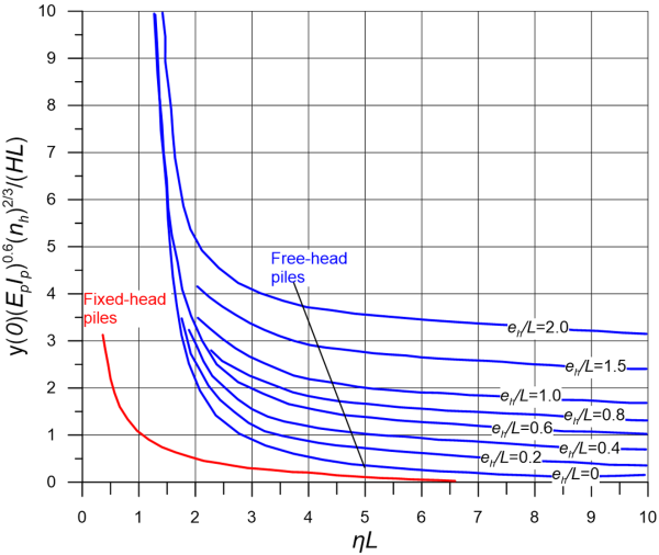
Given the value of Kh, Figure 6.108 can be used to estimate the lateral deflection of free-head and fixed-head piles due to a serviceability lateral load, Hw. The term η is calculated as:
(6.127) 
where Ip is the moment of inertia of the pile’s cross-section, and Ep the Young’s modulus of the pile material. This method provides only lateral pile head deflection, and not pile head rotation, that will develop in free-head piles.
