6.24 Broms method – Piles in undrained soil
6.24.1 Short free-head piles
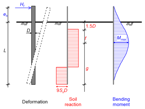
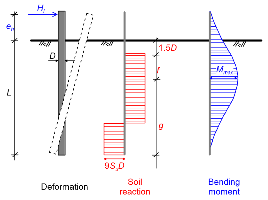
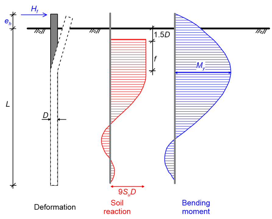
Calculation of the ultimate geotechnical strength (collapse lateral load) of a pile subjected to lateral load H at its head, and of the maximum bending moment Mmax developing along the pile, is based on static equilibrium considerations (Figure 6.95). The ultimate soil reaction (Figures 6.95, 6.96) is taken equal to pf = 9SuD, and is compatible with the exact solution of Randolph and Housbly (1984) mentioned above, if we assume conservatively that the soil-pile interface is smooth.
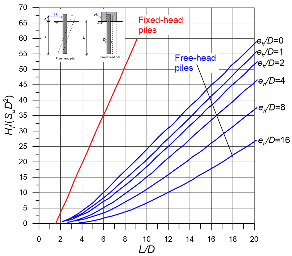
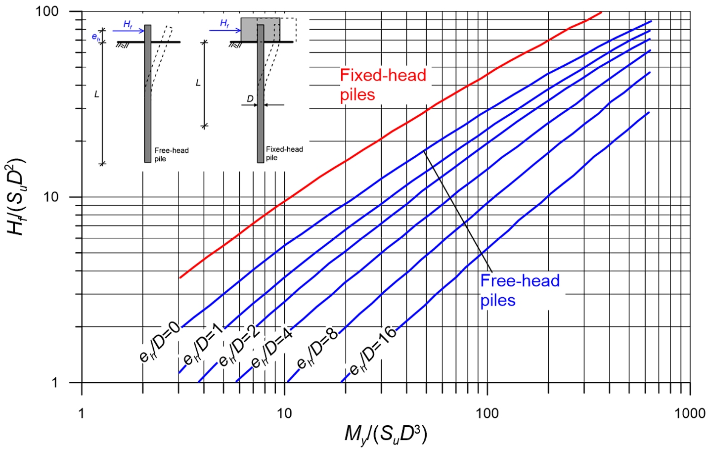
While considering equilibrium, the reaction on the pile from soil developing near the soil surface (length equal to 1.5D) is ignored, because a wedge of soil can move up and outwards when the pile is deflected. Based on that, the ultimate geotechnical strength Hf can be determined from Figure 6.96 as a function of the pile geometry, the elevation of load resultant eh, and the undrained shear strength of the fine-grained soil, assumed constant with depth. Furthermore, the point along the pile where the maximum bending moment will develop (zero shear force) will be at distance f (units: length) from the surface (Figure 6.95):
(6.104) 
Having calculated the collapse lateral load Hf and f, the maximum bending moment that will develop on the pile Mmax is calculated as:
(6.105) 

6.24.2 Short fixed-head piles
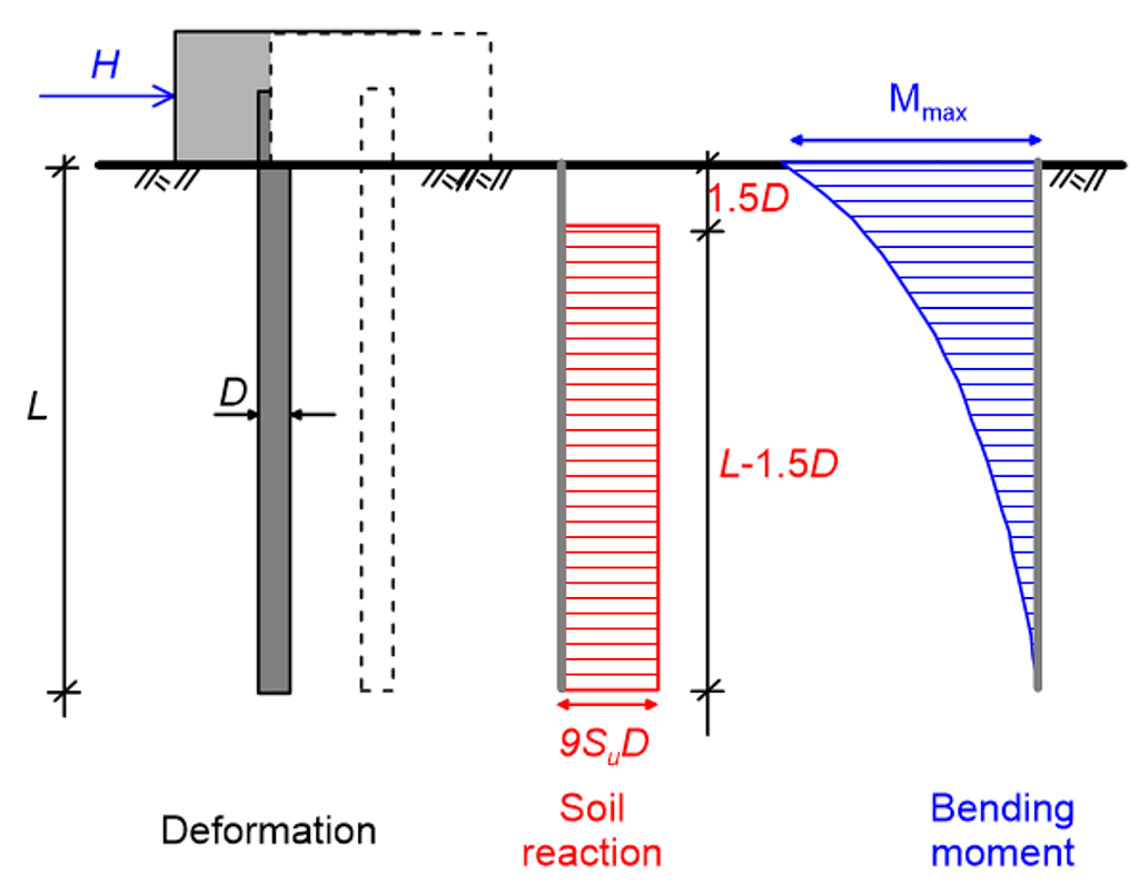
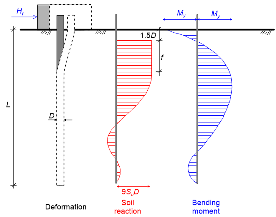
The same procedure is followed for fixed-head piles too, assuming that the ultimate soil reaction develops along the full length of the pile, with the exception of the top 1.5 diameters, where it is customarily ignored (Figure 6.97).
The ultimate lateral load Hult results from the need to satisfy static equilibrium, and can be either found using Figure 6.96, or directly as:
(6.106) 
Similarly, the maximum bending moment Mmax that will develop at the head of the pile, at the connection with the rigid cap, is estimated as:
(6.107) 

6.24.3 Long free-head piles
Long failure mode corresponds to cases where the passive resistance from the soil along the pile length is very high, and before it is full mobilised, the maximum bending moment along the pile will became equal to the plastic (yield) bending moment, My of the pile’s section. Failure will occur with the formation of a plastic hinge at the point where the maximum bending moment develops (Figure 6.98), at a depth equal to 1.5D+f where f is calculated from Eq. 6.104. The collapse lateral load, Hf is determined from Figure 6.99, or directly as:
(6.108) 


The plastic moment, that develops when stresses over the entire cross-section of the pile reach the yield stress of the material, depends on the material properties, the geometry of the cross-section as well as the axial force on the pile, for concrete piles. The plastic moment of some typical cross-section geometries for homogeneous pile material (e.g., steel) are provided in Table 6.14.
| Plastic moment, My | |
|---|---|
| Rectangular cross-section, with width b and height h. |  |
| Circular cross section, with diameter D |  |
| Hollow circular cross section with external diameter Dext and internal diameter Dint |  |
For design purposes, both the short pile and the long pile failure modes must be considered, to find the critical, minimum collapse load. To determine whether the pile will fail as a short pile or as a long pile first, one should start with the expressions in Section 6.24.1 for a short pile. If the resulting maximum bending moment is larger than the yield moment, the formulas for long pile failure must be used, as they will result in lower collapse lateral load.
6.24.4 Long fixed-head piles
As in the case of long free-head piles, the plastic (yield) bending moment, My will be reached before the ultimate soil reaction is mobilised along the full length of the pile. Failure will occur with the formation of two plastic hinges (Figure 6.100): One at the connection of the pile with the cap, where the pile is fixed against rotation, and a second at the point where the maximum bending moment develops, at a depth equal to 1.5D+f where f is calculated from Eq. 6.104. The collapse lateral load, Hf is determined from Figure 6.99, or directly as:
(6.109) 
There is however an intermediate case: A plastic hinge may develop at the head of the pile only, when the bending moment reaches there My. Then the ultimate lateral load will be:
(6.110) 
and the bending moment at a depth equal to 1.5D +f:
(6.111) 
Note that in that case Mmax is lower than the plastic moment Μmax < Μy. For given soil undrained strength and pile section properties, the critical failure mode (long, short, intermediate) that will result in the lowest lateral load depends on the length of the pile.

6.24.5 Pile lateral deflection
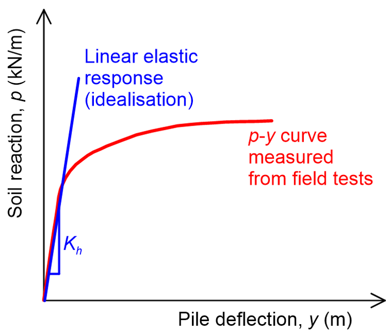
For the calculation of the pile head deflection y(0) at serviceability conditions, soil is assumed to behave as linear elastic material (see Figure 6.90). Besides, good design practice suggests that piles should be designed so that soil strains under serviceability lateral loads remain low. In line with Figure 6.90, a key parameter for the estimation of the lateral deflection of piles is the slope of the linear p–y curve Kh, which is referred to as coefficient of subgrade reaction or soil reaction modulus (units: stress/unit length).
A limitation of Brom’s method is that Kh must be estimated by means of empirical formulas. A more rigorous solution that forgoes this requirement is presented later in this Part. For overconsolidated clays, we can assume for simplicity that Kh is not depth-dependent, and can be estimated as:
(6.112) 
where Eu is the undrained Young’s modulus of clay, which should be compatible with the level of the applied strain due to the lateral soil displacement. Alternatively, Davidson (1972) proposed to estimate Kh as a function of the undrained shear strength of clay, as:
(6.113) 
Some typical coefficient of subgrade reaction values for overconsolidated clays are listed in Table 6.15.
| Undrained shear strength range | |||
|---|---|---|---|
| 100 < Su < 200 kPa | 200 < Su < 400 kPa | Su > 800 kPa | |
| Range of Kh values (kN/m3) | 12000 to 24000 | 24000 to 48000 | 48000 to 96000 |
| Recommended Kh value (kN/m3) | 18000 | 36000 | 73000 |
The coefficient of subgrade reaction generally increases with depth, z in normally consolidated clays. For simplicity, we can assume linear increase of Kh with z, as:
(6.114) 
where nh is a factor that ranges between nh = 350 to 700 kN/m3. Alternatively, Eq. 6.113 can be used for normally consolidated clays too, with some conservatism. The increase of undrained shear strength with depth can be introduced in Eq. 6.113, hence considering the increase of Kh along the pile length in the calculations.
Note that the above formulas for the estimation of the coefficient of subgrade reaction, as well as the typical values, apply to static, monotonic lateral loads. For dynamic loads with a low number of loading cycles (e.g., seismic loads) one should adopt a higher value of Kh,dynamic=2 to 3Kh.
According to Broms, the coefficient of subgrade reaction should be estimated as the average over a depth 0.5βL, where β is:
(6.115) 
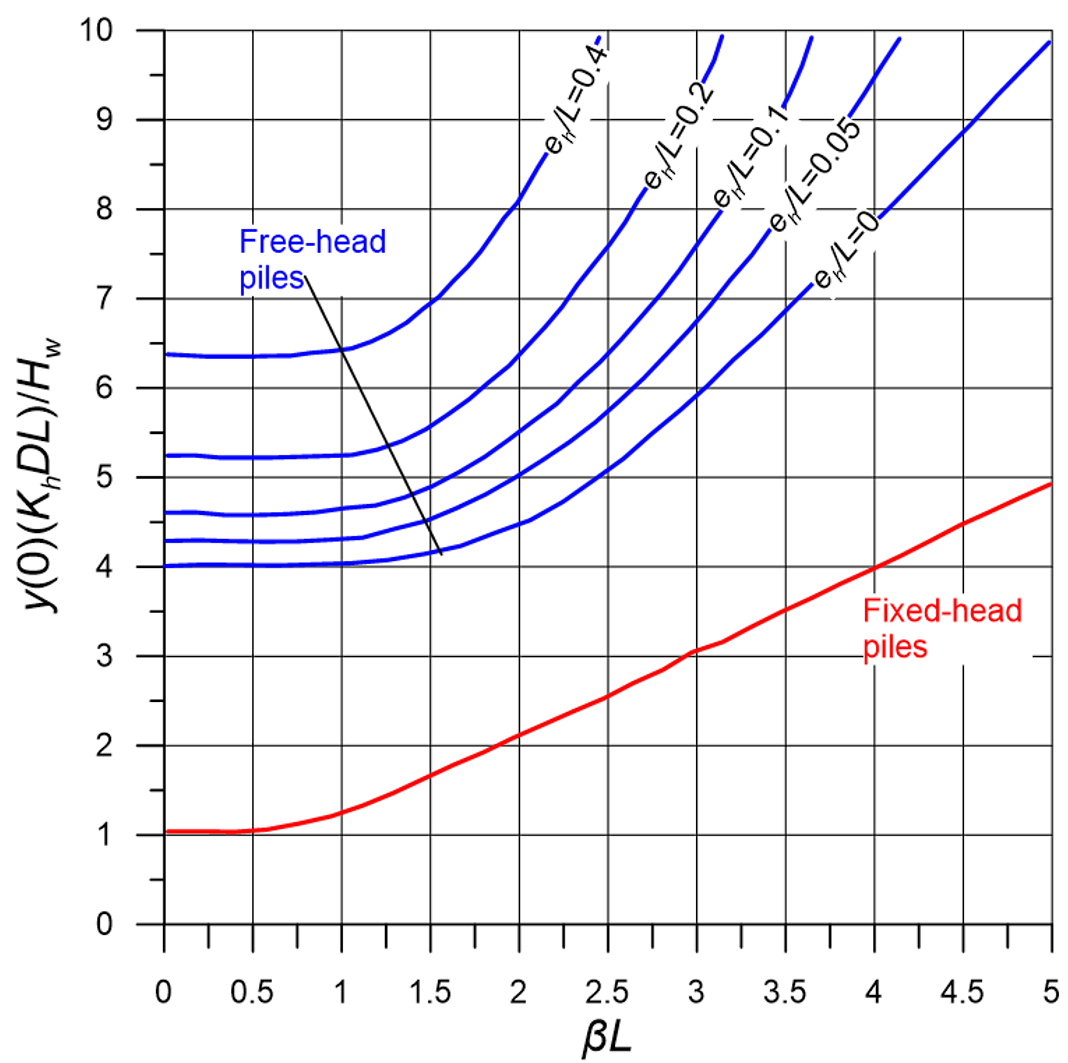
where Ip is the moment of inertia of the pile’s cross-section, and Ep the Young’s modulus of the pile material. Given the value of Kh and factor β from Eq. 6.115, Figure 6.101 can be used to estimate the lateral deflection of free-head and fixed-head piles due to a serviceability lateral load, Hw. As discussed before, the provided coefficient of subgrade reaction modulus values, and the methodology for estimating pile displacements are valid for a working load that is one-third up to one-half the collapse lateral load of the pile, Hf.
Finally, it should be noted that free-headed piles will rotate as well as deflect upon application of a lateral load. A method for calculating pile head rotation is presented later in this Part.

