6.23 Lateral loading of piles – General considerations
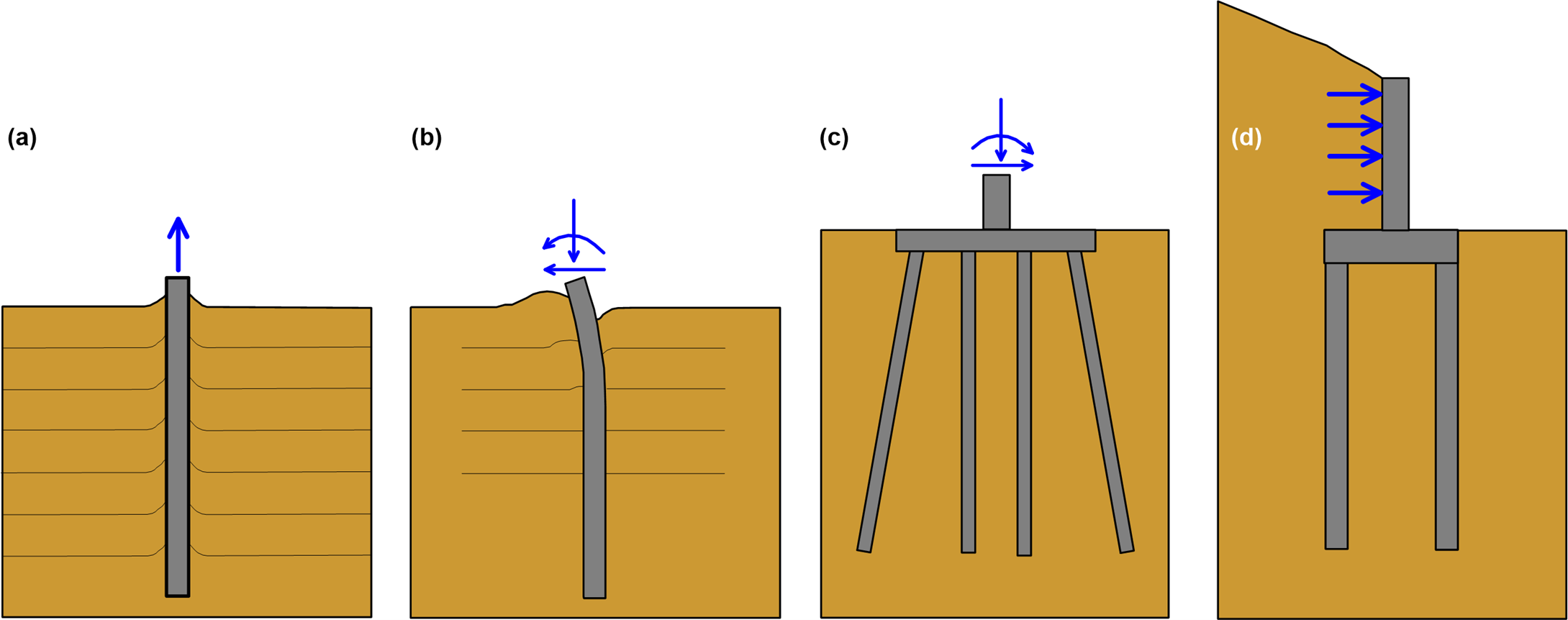
One of the main advantages of pile foundations, compared to shallow footings, is their ability to sustain high lateral forces and bending moments (Figures 6.2b-6.2d) due to seismic actions, wind pressure, vehicle acceleration and braking loads, wave loads etc. Design of piles to resist lateral loads is a soil-structure interaction problem, where the response of the superstructure, the pile and the soil must be jointly considered.
Development of methodologies for the design of piles against lateral loads has its origins back in the 1950’s, when exploitation of offshore resources commenced. Most of the methods are based on the interpretation of measurements obtained during full-scale experiments on instrumented piles subjected to static and cyclic lateral loads. Lateral load tests on piles, especially cyclic load tests are less common, as they are much more expensive than compressive static load tests discussed in Chapter 6.16, and they are performed only in special projects.
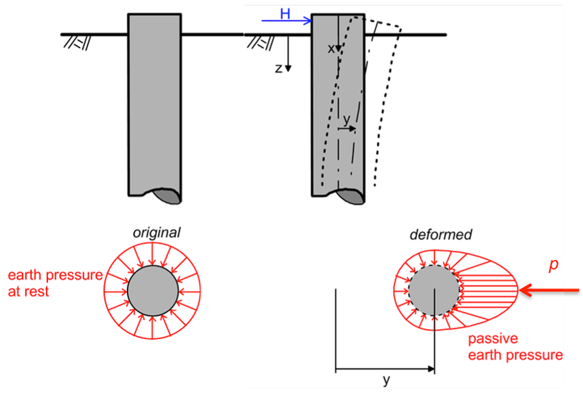
After installation of the pile, the horizontal ground stresses developing around its cross-section can be assumed uniform, and are often taken equal to the geostatic earth pressure at-rest as e.g., in the β-Method described in Chapter 6.10 (Figure 6.89). As the pile deflects under the application of a lateral load H by y, the distribution of stresses changes: the soil stresses applied at the front side of the pile increase (passive earth pressure state) and the soil stresses applied at the back side of the pile decrease (active earth pressure state).

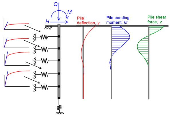
The soil-related parameter governing the design of a pile under lateral loading is the reaction modulus p/y defined as the reaction p from the soil at a point along the pile, divided by the deflection of the pile at the same point y. The reaction, or soil resistance p results from integration of stresses along the cross-section (Figure 6.89), and its dimensions are force per unit length along the pile.
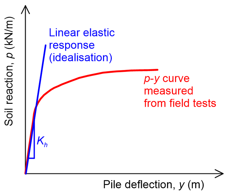
The reaction p is a function of the soil and pile properties, the depth below the ground surface z, and the deflection of the pile, y. Notice that in reality, the magnitude of the soil resistance varies significantly with pile deflection: the p-y curve is actually non-linear (Figure 6.90). However, an equivalent linear approximation of the p-y curve is often used in design, particularly for serviceability analysis where pile deflection is of interest, and soil-pile interaction is described by a single parameter: the slope of the idealised curve, or the coefficient of subgrade reaction Kh (Figure 6.90).
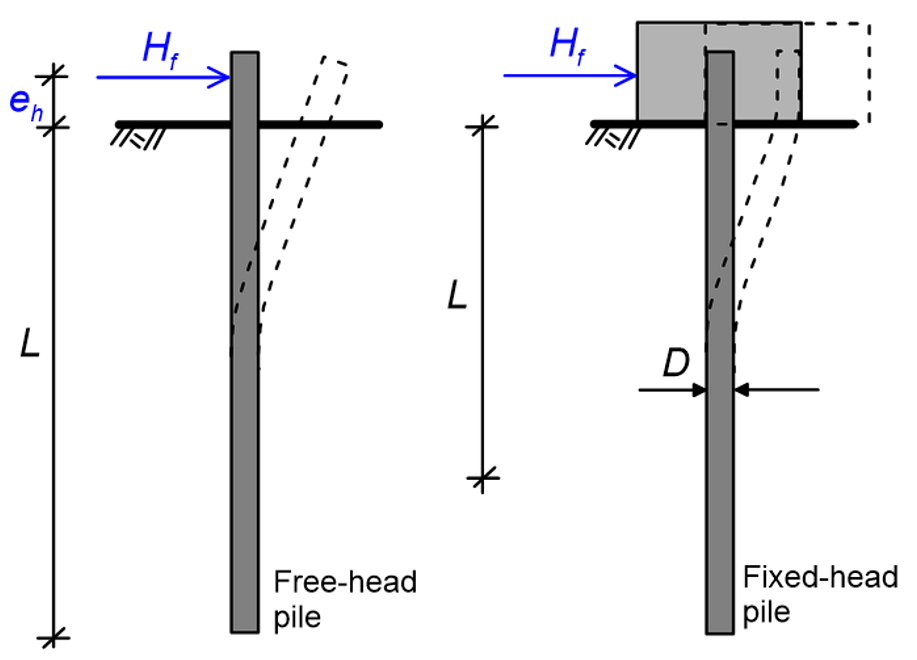
When a pile is subjected to a combination of lateral force and bending moment at its head (Figure 6.91), the following must be ensured via proper engineering calculations and checks:
- The lateral capacity of the soil must not be exceeded.
- Displacements and rotations of the pile head must not affect the serviceability of the structure.
- The developing axial force and bending moment must not exceed the structural strength of the pile cross-section.
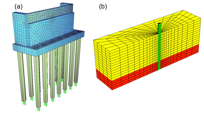
Non-linear (or equivalent linear) p-y curves can be introduced in a simple beam-spring finite element model, to determine pile deformation and internal forces under a combination of loads (Figure 6.91). This method is described later in this Part, as it is widely used in practice. Instead of applying the loads directly on the pile head, the superstructure (e.g. bridge pier) may be modeled too, to account for soil-pile-superstructure interaction effects (Figure 6.92a). Of course, more elaborate 3-D models of the pile embedded into the soil system may be used for the most accurate simulation of the soil-pile system response (Figure 6.92b), but their use is limited to special projects or for research purposes.

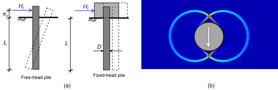
As described in the following paragraphs, simpler methods that do not require the use of a computer may be also applied, at least to obtain a first-order estimate of the pile response. According to AS2159, the ultimate geotechnical strength (collapse lateral load, Hf) of a pile subjected to lateral loading shall be determined as the minimum of the following two values:
- The ultimate geotechnical strength for “short pile” failure (Figure 6.93a), developing when the ultimate reaction from soil is mobilised uniformly along the entire length of the pile (soil fails first). The later is assumed to translate or rotate as a rigid body, depending on the fixity conditions at its head. The ultimate soil reaction per unit length of a pile in undrained perfectly-plastic soil been calculated by Randolph and Houslby (1984) using the upper and lower bound plasticity theorems described in Part 5. For “smooth” soil-pile interface (see Chapter 6.9) the exact plasticity solution for the ultimate reaction is pf = 9.14SuD, while for “rough” soil-pile interface pf = 11.94SuD (Figure 6.93b).
- The ultimate geotechnical strength for “long pile” failure (Figure 6.94), developing when the structural strength of the pile section is reached at some point along the pile shaft, and a plastic hinge is formed before the ultimate soil reaction is mobilised along the entire length of the pile (pile fails first).

The type of failure that will eventually develop depends on the relative rigidity of the pile, compared to the surrounding soil. A method that appropriately considers both “short pile” and “long pile” failure modes was develop by Broms (1964a,b, 1965), based on the following assumptions: a) Rigid pile and uniform, perfectly plastic soil, for the estimation of the ultimate geotechnical strength and associated pile bending moment, and b) Linear elastic soil, for the estimation of pile deflection under the serviceability load. Broms developed different solutions for uniform soil and both undrained and drained loading conditions, but not for layered soil profiles. Notice that the response of the pile depends also on the fixity conditions at its head (Figures 6.93–6.94).
Although it is based on a number of simplifying assumptions, Broms method can be useful for the initial selection of the pile cross-section and length, and can act as springboard for more detailed finite element analyses. It must be noted that since lateral loads on piles often act for a short period of time (seismic, wave, wind, vehicle loads), low permeability soils such as clay are almost exclusively treated as undrained.
It is worth concluding this section by noting that, while in AS2159 there is no mention of a “preferable” failure mode, in the author’s view piles generally should not be designed to fail with a “short” failure mode: The redundancy of the soil-pile system is zero if the ultimate lateral reaction of soil is reached along the full length of the pile, and failure will result in excessive pile lateral displacement and perhaps collapse of the supported structure. On the other hand, plastic hinge(s) that will develop in a soil-pile system that has been designed to fail with a long failure mode will feature some over-capacity, and catastrophic collapse will probably be avoided.
