6.22 Negative skin friction effects
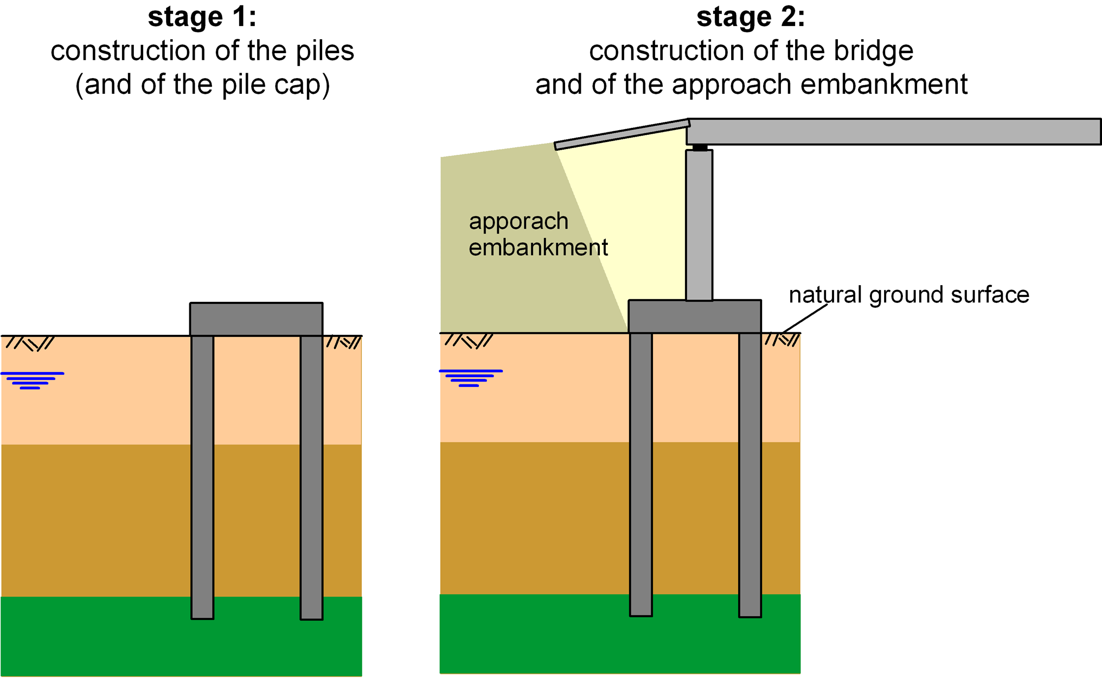
Let’s consider the case where a load is applied on the ground surface in the vicinity of a pile, or a pile group, after the construction of the piles has been completed. A common case where these conditions are met in practice is the construction of a bridge approach embankment, which follows the construction of the bridge foundation (Figure 6.80).
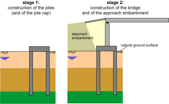
The approach embankment will impose a surcharge on the soil, and the soil adjacent to the pile will begin to settle. If the magnitude of the surcharge, or the compressibility of the surficial soil layers, is high the soil around the pile will settle more than the pile settles while transferring the axial compressive load from the superstructure.
Remember that skin friction develops on the pile shaft to resist the relative vertical displacement of the pile resulting from the load imposed on its head, Q. For the sake of generality we will drop the subscript w in this chapter and refer to the load on the pile head as Q although, as discussed later, negative skin friction is a serviceability problem, and pile settlement due to negative skin friction must be estimated while considering the serviceability load acting at the pile’s head. Along the pile length where ρpile < ρsoil, the developing skin friction will have an opposite sign, compared to the skin friction at the lower part of the pile (negative skin friction). Thus, instead of contributing to the pile resistance, the friction along the upper part of the pile will add to the external load (Figure 6.81):
(6.103) 
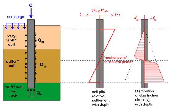
If we plot the distribution relative soil-pile displacement ρsoil–ρpile along the pile shaft, we will find the point where the relative displacement becomes zero, or ρpile = ρsoil. This point is called the “neutral point” or “neutral plane”. Above the neutral plane skin friction stresses are negative, adding to the external load, and below the neutral plane friction stresses are positive, and contribute to pile resistance (Figure 6.81).
Estimation of the location of the neutral plane is necessary for the estimation of the negative and positive friction load and resistance of the pile, respectively. This is not a straightforward process, as it depends on a number of parameters.
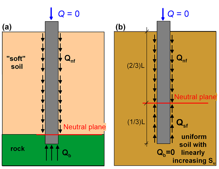
Provided that the soil strength increases with depth, as in most common cases, the neutral plane will be found somewhere below the mid-point of the pile, if the external load applied at the pile head is zero (Q = 0). In the extreme case where the pile toe is founded directly on a practically incompressible layer of rock, the neutral plane will be located at the elevation of the bedrock (Figure 6.82a). In the case of a friction pile in uniform soil, which shear strength increases linearly with depth, the neutral plane will lie near the lower third of the pile (Figure 6.82b), if the pressure transferred to the pile toe is negligible, which is reasonable under serviceability conditions.

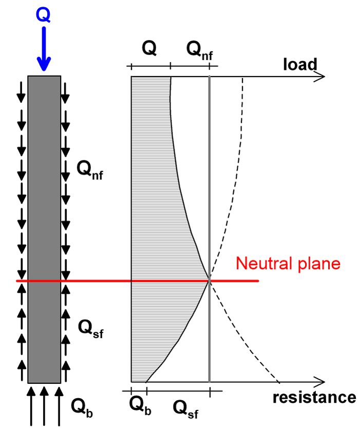
However, the above are valid if no vertical load is applied on the pile. Following the application of an axial compressive load at the pile head Q, the pile will settle further. Consequently, the neutral plane will move up, and the magnitude of the dragload, defined as the sum of the negative skin friction shear stresses along the interface, is reduced. In other words, negative skin friction also depends on the load applied on the pile under serviceability conditions. As depicted in Figure 6.83, the location of the neutral plane is found at the intersection of two load distribution curves (Fellenius, 1984):
- of the forcing load distribution curve, which is drawn from the pile head downwards, starting from the applied axial compressive load Q, and adding the load due to negative skin friction Qnf, with the latter taken as acting along the entire length of the pile.
- of the resistance load distribution curve, which is drawn from the pile toe upwards, starting from the value of the end bearing resistance Qb, and adding the resistance due to positive skin friction Qf, with the latter taken again as acting along the entire length of the pile. Note that under serviceability conditions Qb can be considered to be zero, as it is not at all certain that sufficient pressure has been transferred to the pile toe.

While drawing the abovementioned curves, the skin friction resistance must be estimated while considering drained soil behavior (β-method or ICP method, Chapter 6.10 and Section 6.12.7), as excess pore pressure at the end of consolidation will have dissipated.
Some key points that must be taken into account while considering negative skin friction effects:
- The structural capacity of the pile to resist axial compressive forces must be checked at the location of the neutral plane. Generally, the axial capacity of the cross-section will be higher than the sum of the serviceability load and the negative skin friction, and this check should not be critical.
- The dragload must not be included in the consideration of the ultimate geotechnical strength i.e., the load applied on the pile head should not be reduced by any portion of the dragload: In the Ultimate Limit State, when the collapse load is reached, the pile will move downwards along its entire length, and negative skin friction is eliminated. In that case, the neutral point will be found at the pile head. Of course, if settlement of the pile head due to negative skin friction is large enough to cause failure of the superstructure, then the ULS criteria will not be met. However, in that case settlement of the pile under serviceability conditions will not be acceptable either.
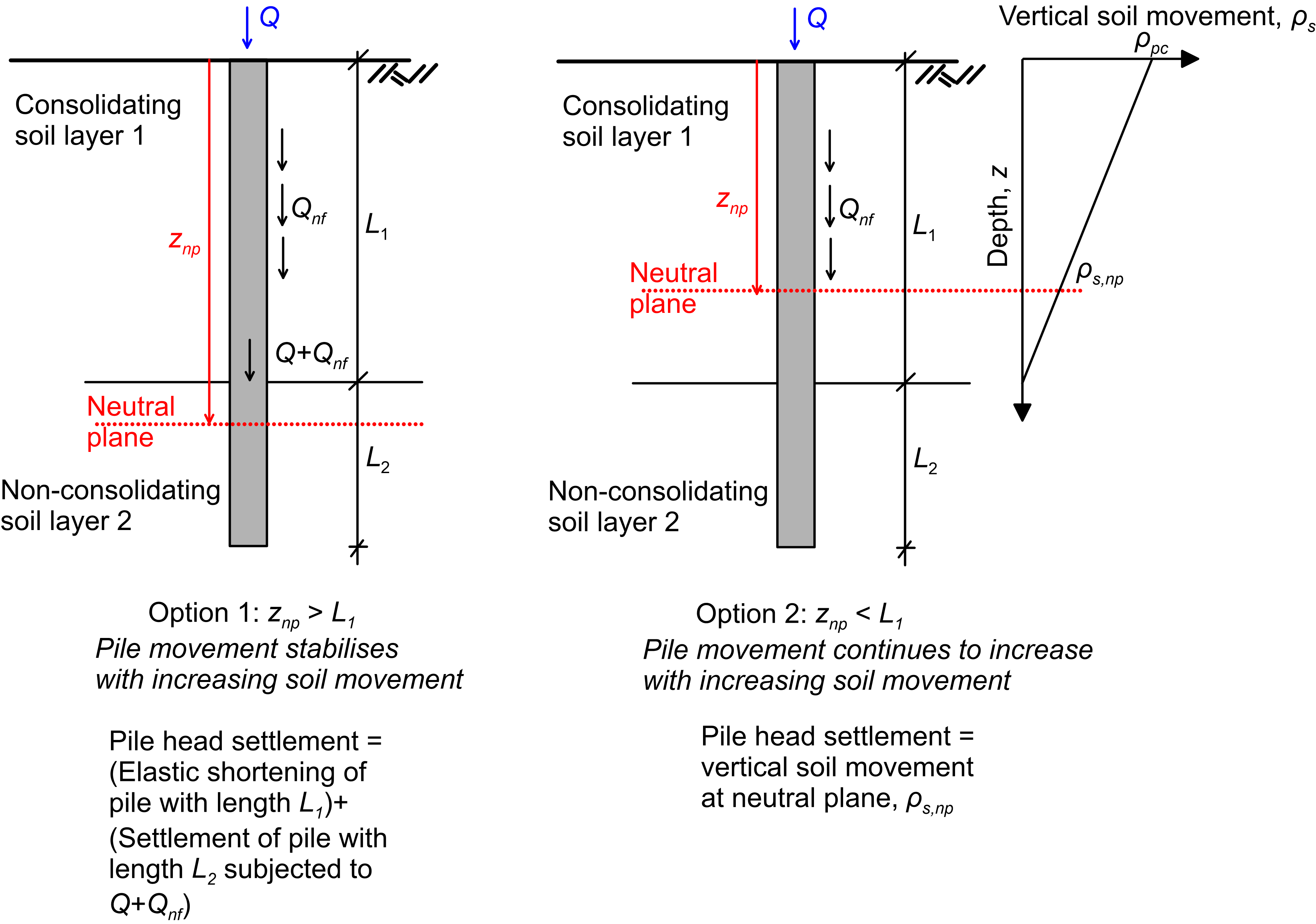
- Negative skin friction is rather a settlement problem. Consider the problem depicted in Figure 6.84, where a pile is installed in a two-layer profile consisting of a consolidating layer 1 and a non-consolidating layer 2. The neutral plane will be found at a depth znp which may be larger than the thickness of layer 1 (znp > L1, Option 1, Figure 6.84), or smaller (znp < L1, Option 2, Figure 6.84). Poulos et al. (2001) recommend calculating the depth of the neutral plane with the Fellenius (1984) method outlined above. Accordingly, settlement of the pile head (which should be calculated for serviceability conditions) is estimated as the larger of: i) The elastic compression of the portion of the pile embedded in layer 1 (Length L1, Figure 6.84) plus the settlement of the portion of the pile embedded in layer 2. The latter can be calculated using the methods described in Chapters 6.20 and 6.21, while considering a pile of length L2 (Figure 6.84) equal to the thickness of layer 2 and compressive load equal to Q = Qw + Qnf; ii) The free-field movement of the soil at the level of the neutral plane ρs,np (Figure 6.84). This settlement is calculated with conventional methods (Part 4), ignoring the existence of the pile. While this is not mentioned in Poulos et al. (2001) the author recommends adding to the free-field movement of the neutral plane ρs,np the elastic shorting of a portion of the pile with length znp. This may or may not be important.
- Inclined (battered) piles should be avoided in areas where negative skin friction development is expected, as large soil settlement will induced excessive bending of inclined piles.

There are several methods to reduce negative skin friction effects, such as (FHWA 2006):
- Reduction of the soil settlement e.g., by preloading soil or implementing other soil improvement methods, or even using lightweight fill material (EPS geofoam) for the core of the approach embankment.
- Treatment of the piles with a friction reducer, such as bitumen or plastic wrap. This method will work only for drilled shafts.
- Use pile sleeves to prevent direct contact between the soil and the pile.
- Alter the construction sequence, so that no consolidation settlement takes place after the construction of the piles.
Concluding, negative skin friction will develop whenever differential settlement develops between the soil surrounding the pile, and the pile itself, regardless of the cause of settlement. Thus, in cases where consolidation settlement is possible due to e.g., lowering of the water table as a result of groundwater overpumping (Chapter 4.2), construction of an adjacent foundation that will impose additional stresses in the soil or seismic liquefaction, the possibility of the development of negative skin friction must be examined.
