6.20 Immediate settlement of pile groups
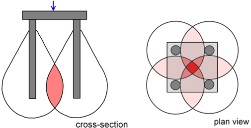
Interaction between piles in a group and stress overlapping (Figure 6.64) tends to affect pile settlements, so the settlement of a pile group subjected to axial compressive load is not equal to the settlement of a single pile carrying the same average load. Pile group settlement is generally influenced by the spacing between the piles, the number of piles in the group, and the slenderness ratio L/D. Two families of methods for predicting settlement of a pile group consisting of arbitrary number of piles are presented in the following.
6.20.1 Approximate methods for piles connected with a rigid cap
To calculate settlement of a group of piles spaced at s/D > 2.5 (s is the centre-to-centre pile spacing) and connected with a rigid cap, a first-order approximation is to assume that the vertical compressive load acting at the cap is distributed equally among all piles in the group. In that case we can use the following formula to get an estimate of the settlement of the piles, which of course will settle uniformly (Fleming et al. 1985).
(6.96) 
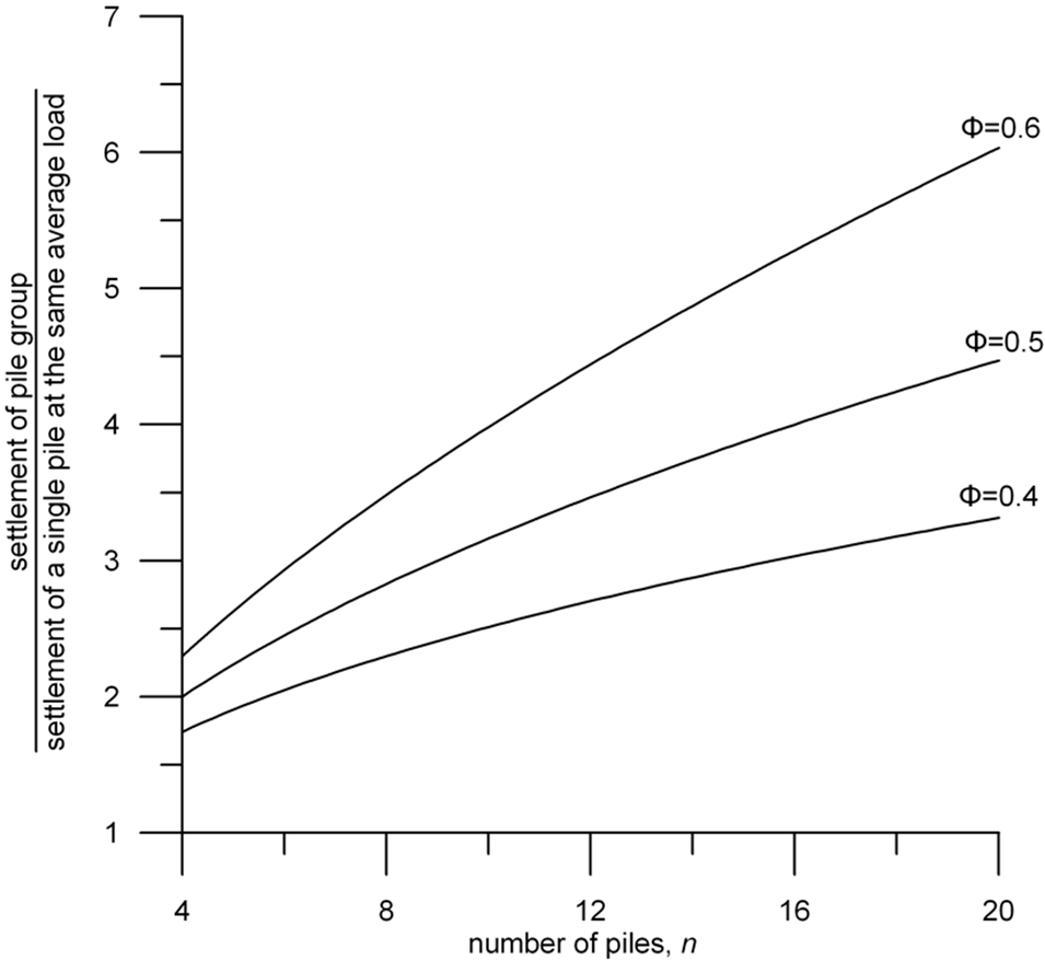
where n is the number of piles in the group and the factor Φ ranges between 0.4 and 0.6 (Figure 6.76).

According to Poulos (1989), comparisons with pile load tests suggest that Eq. 6.96 provides reasonable results for Φ = 0.5. Values of the factor Rs for common pile groups comprising 8-to-16 piles lie in the range of Rs = 2.8 to 4, suggesting that settlement of pile groups can be considerable, compared to settlement of individual piles.
Alternatively, the equivalent pier method can be used (Poulos, 1993). In this method, the pile group is replaced by a pier of similar length to the piles of the group, featuring an equivalent diameter, De:
(6.97) 
where AG is the plan area of the pile group, including the soil between the piles. The lower value of De applies to predominantly end-bearing piles, while the upper value should be considered for friction piles. Accordingly, the methodology for single piles is followed, assuming the pier is working as a single pile. Generally, both the Fleming et al. (1985) and the equivalent pier methods will result to comparable pile group settlement estimates.
6.20.2 Elasticity method for piles connected with flexible or rigid cap, accounting for load distribution
The are several solutions in the literature that can be used to predict the settlement and the distribution of axial loads in floating and end-bearing groups of piles, that require little computational effort-at least for static loads. These are based on certain important assumptions, such as elastic soil behaviour, no slippage at the soil-pile interface or incompressible soil (soil Poisson’s ratio vs = 0.5). Nevertheless, it has been demonstrated in the literature (e.g. Poulos and Mattes 1971) that, despite their simplicity, elasticity-based methods can provide reasonably accurate estimates of pile group behaviour in the field, as under serviceability conditions non-linearity effects are not particularly important.
Many of the mentioned solutions used in practice are based on the interaction factor αi (or its variants), first conceived by Harry Poulos and his co-workers at the University of Sydney:
(6.98) 
For a two-pile group consisting of friction or end-bearing identical piles, elastic settlement of a pile that accounts for group effects ρi can be calculated while considering pile-to-pile interaction as:
(6.99) 
where the elastic settlement of the pile under its own load (ρe) can be calculated using the elasticity-based methods described in the previous Chapter 6.20.
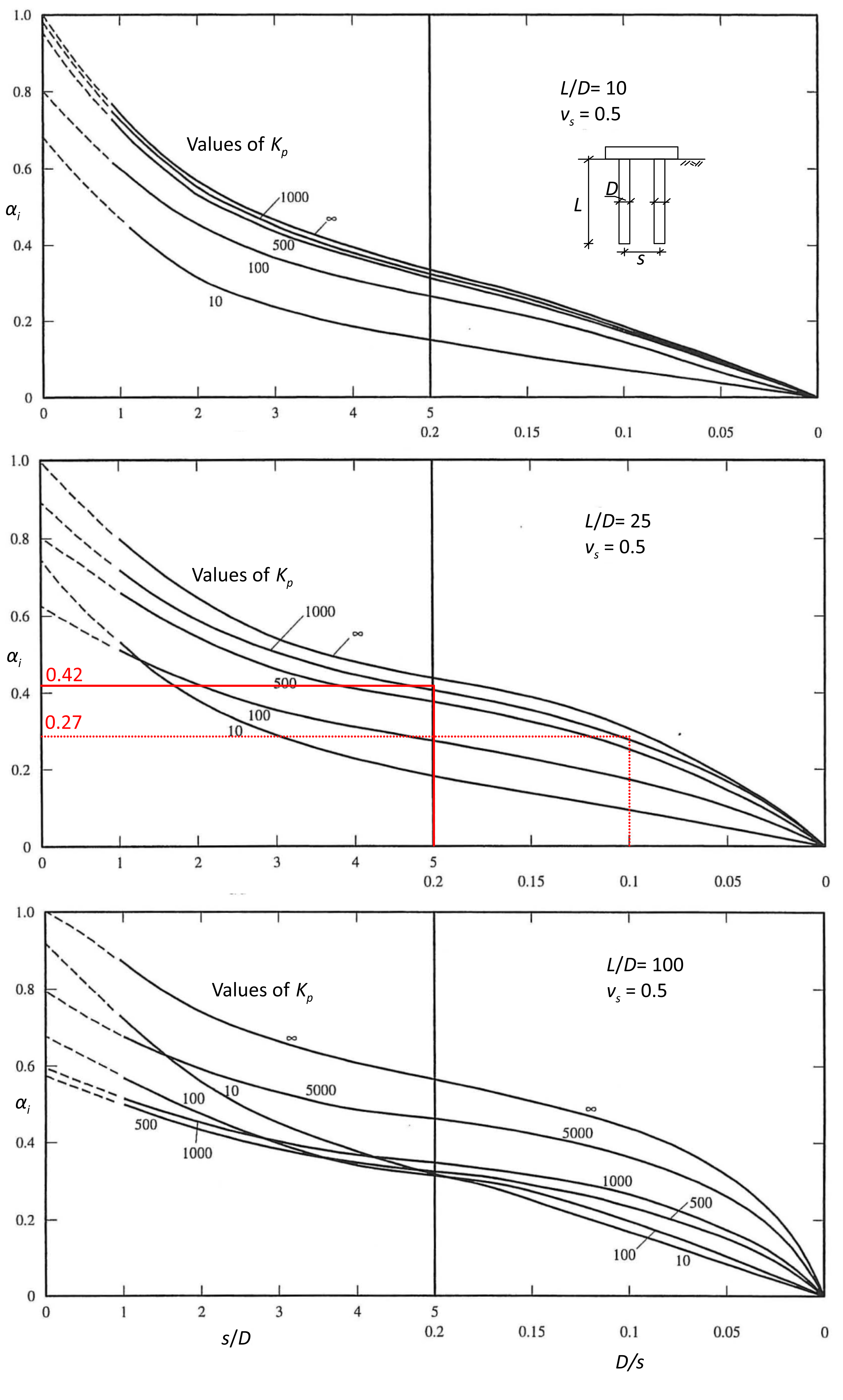
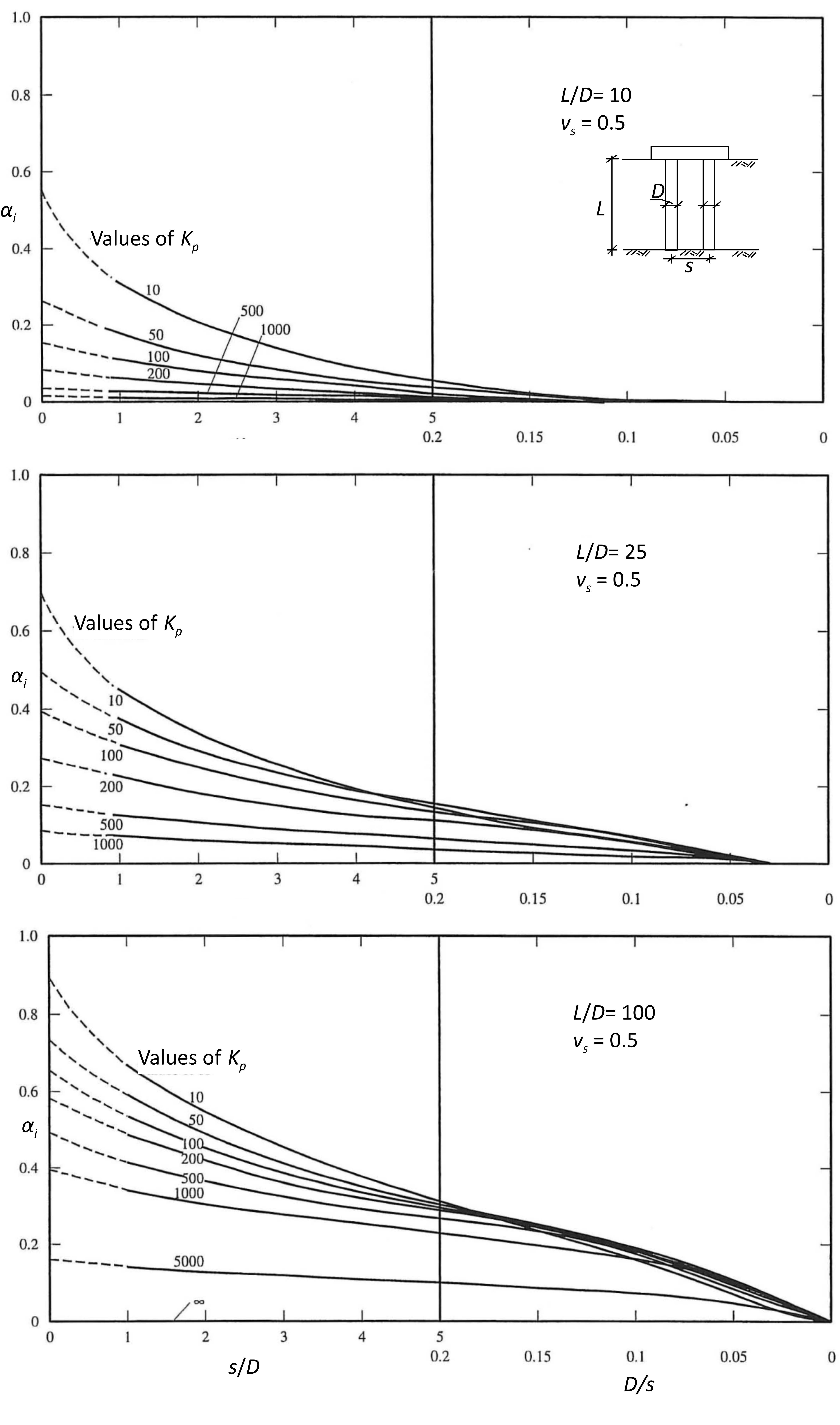
The interaction factor αi for a two-pile group is given by the charts prepared by Poulos (1968) and Poulos and Mattes (1971) and presented in Figures 6.77 and 6.78, for floating and end-bearing pile groups embedded in undrained soil (vs = 0.5) respectively. In these charts Kp is the pile stiffness factor, as piles are considered as elastic 1D rods (i.e., are not rigid), and is calculated according to Eq. 6.93.
The two-pile group interaction factors can be used to obtain the settlement and load distribution in a pile group consisting of arbitrary number of identical circular piles connected with rigid or flexible cap, by exploiting the principle of elastic superposition. The settlement of any pile i in a group of k identical piles is:
(6.100) 
where: ρ1 is the elastic settlement of a single pile under unit load, αi,ij is the interaction factor for spacing s between piles i and j (from Figure 6.77 or Figure 6.78), Qw,i is the serviceability load on pile i, and Qw,j is the serviceability load on pile j. Casting the above equation for all piles in a group results in a system of linear equations, that can be solved if we consider:
1. Equilibrium of forces
(6.101) 
where Qw,group is the total axial compressive load acting on the pile cap for serviceability conditions.
2. Equal settlement of all piles, if they are connected with a rigid pile cap, or
3. Equal load on all piles, if they are connected with a flexible pile cap, thus the load will be distributed uniformly.
It is reminded here that this method does not account for the (additional) settlement of the compressible soil layer underneath the toe of floating piles groups. This needs to be calculated separately according to the mentioned in the next section.
Application of the method is demonstrated in the worked example that follows. Note that his method is not applicable to piled rafts i.e., we assume that no load is transferred to soil through the pile cap.


