6.18 Pile group effects on ultimate geotechnical strength
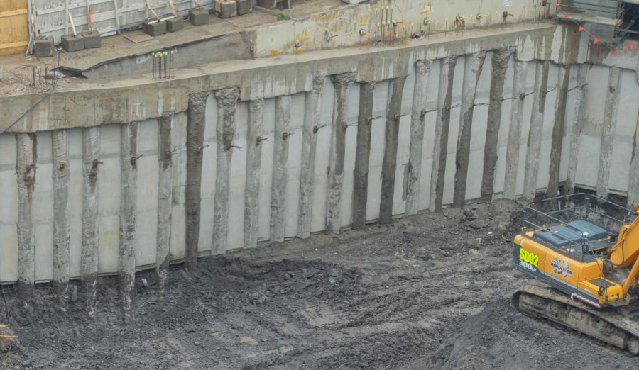
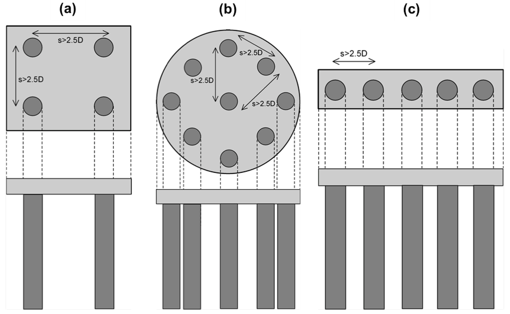
In most practical cases, except of some special structures such as lighting poles or wind turbines, multiple piles arranged in groups are used for the foundation of structures. Piles are arranged in square, rectangle, circular groups, or in pile rows and their heads are connected via a reinforced concrete pile cap of adequate thickness (Figure 6.63).
Piles groups feature considerable lateral stiffness, which renders them the most efficient foundation solution when large lateral loads or bending moments must be transferred to the subsoil due to e.g., seismic or wind actions or lateral earth pressures.
Additionally, pile groups have the capacity to carry high vertical loads, although the load capacity of a pile group is not necessarily equal to the load capacity of a single pile multiplied by the number of piles in the group. The pile group efficiency, ng is defined as the ratio of the ultimate geotechnical strength of a group of n piles, Qf,group to the sum of the ultimate geotechnical strength of the individual piles comprising the group, Qf. In most common cases where all piles in the group feature the same ultimate geotechnical strength:
(6.87) 
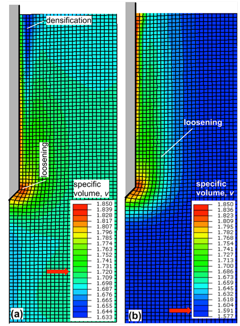
The pile group efficiency ng can be higher or lower than 1, meaning that the bearing capacity of the pile group can be less or greater than the sum of the capacities of the individual piles. Pile group efficiency ng < 1 is possible in piles driven into soft clay/silt or dense sand/dense gravel formations, while group efficiency ng > 1 can be attained when piles are driven into loose sand/loose gravel formations, due to densification of soil around the piles during driving (see for example Figure 6.20). To achieve pile group efficiencies higher than unity, the centre-to-centre spacing of the piles in the group must be dense, generally s < 3D (Figure 6.63). However, installation of piles with such dense spacing is not recommended, due to constructability issues. According to AS2159, spacing s < 2.5D is not recommended, unless “an analysis of interaction effects indicates that overall pile group performance is not adversely affected”. When s > 3D, the piles perform essentially as individual under vertical compressive loads (ng = 1), and the bearing capacity of the pile group can be taken as equal to the sum of capacities of individual piles.

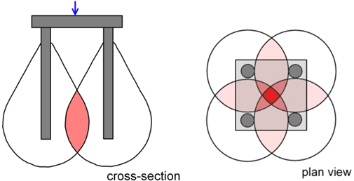
In fine-grained soils, pile group efficiency ng < 1 may need to be considered, to account for overlapping zones of shear deformation in the soil surrounding the piles (Figure 6.64). FHWA (2006) recommends:
- If the pile cap is in firm contact with the ground, consider ng = 1.
- If the pile cap is not in firm contact with the ground as in the case of e.g., an offshore platform foundation, and the undrained shear strength of the fine-grained foundation soil is Su < 100 kPa, a group efficiency ng = 0.7 should be considered in the calculation when the center-to-center pile spacing is s = 3D. When the spacing is greater than s = 6D, ng = 1 can be considered. Linear interpolation can be used to obtain ng for intermediate spacing values:
(6.88) 
- As above, spacing s should not be less than s < 3
Note that pile driving operations can result in generation of excess pore pressures, that could lead to temporary pile group efficiencies of ng = 0.4 to 0.8 immediately after construction. As excess pore pressures dissipate, the efficiency will increase to its normal value. If the foundation will be loaded with the full load shortly after its construction, this effect must be taken into account while determining the ultimate geotechnical of the pile group.
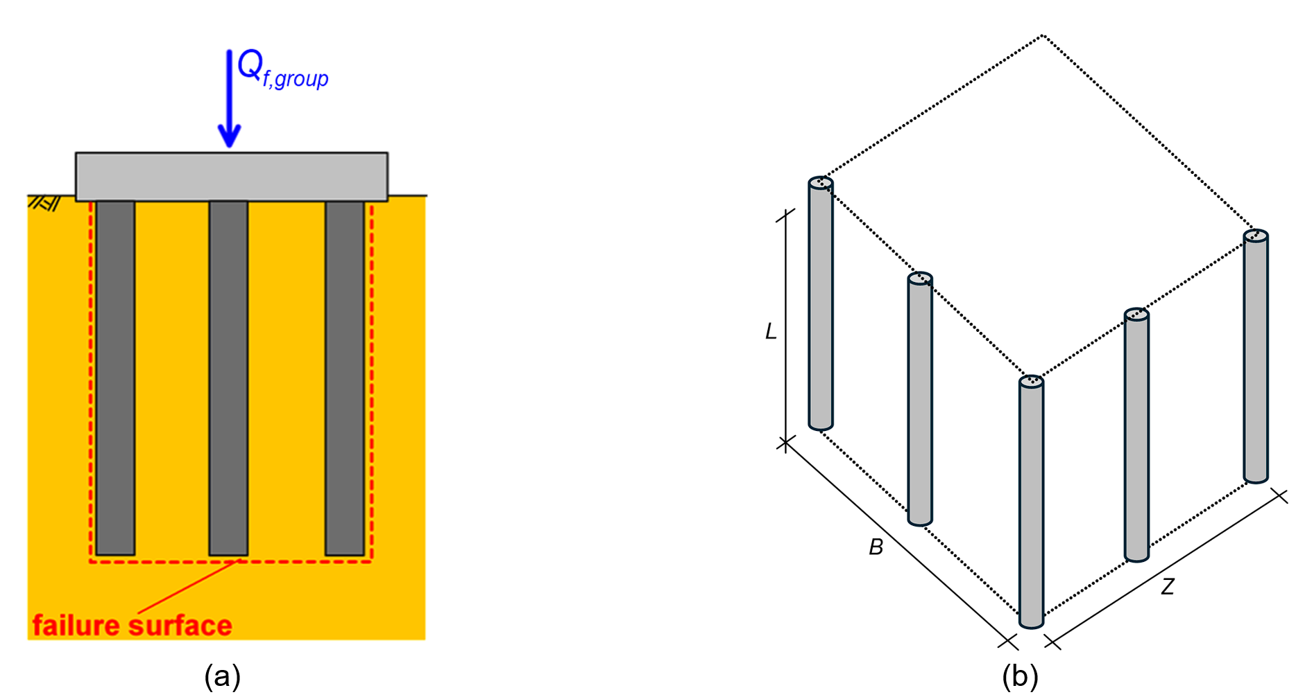
When estimating the ultimate geotechnical strength of a pile group, the possibility of a general, block-type failure mode must be also considered, as described in AS2159. When the pile spacing is generally small, the pile group may fail as a block containing the piles and the soil between them (Figure 6.65a). This type of failure can occur in pile groups installed in fine-grained soils, but also in pile groups founded in a layer of dense coarse-grained soil of limited thickness, when it is underlain by a soft fine-grained layer.

The ultimate geotechnical strength of a pile group against block failure is estimated as:
(6.89) ![{Q_{f,group}} = {S_{u,ave}}\left[ {2L\left( {B + Z} \right)} \right] + {N_{cp}}{S_{u,b}}\left( {BZ} \right)](https://oercollective.caul.edu.au/app/uploads/quicklatex/quicklatex.com-d1cab554e055bb8994ec40072fe4c8b9_l3.png "Rendered by QuickLaTeX.com")
where B is the width of the pile group (Figure 6.65b); Z is the length of the pile group (Figure 6.65b); L is the length of the piles; Su,ave is the average undrained shear strength of the soil along the length L; Su,b is the average undrained shear strength at the base of the pile group up to a depth of 2B below the pile toe level; Ncp is the bearing capacity factor for undrained conditions defined in Chapter 6.9.
