6.1 Introduction to Part 6
There are situations where shallow foundations are proven inefficient or uneconomical for transferring loads from the structure to the subsoil. For example, bearing capacity and/or settlement calculations do not satisfy the relevant acceptance criteria, and any ground improvement methods (preloading, replacement of surficial soil with foundation improvement layer etc.) are either not effective, or too expensive. Pile foundations, which embedment depth is large compared to the width of the foundation, are designed to safely transfer the load from the structure through unsuitable subsoil layers to deeper, suitable bearing strata. In the following, some typical situations when deep foundations are used are compendiously described.
Case 1:
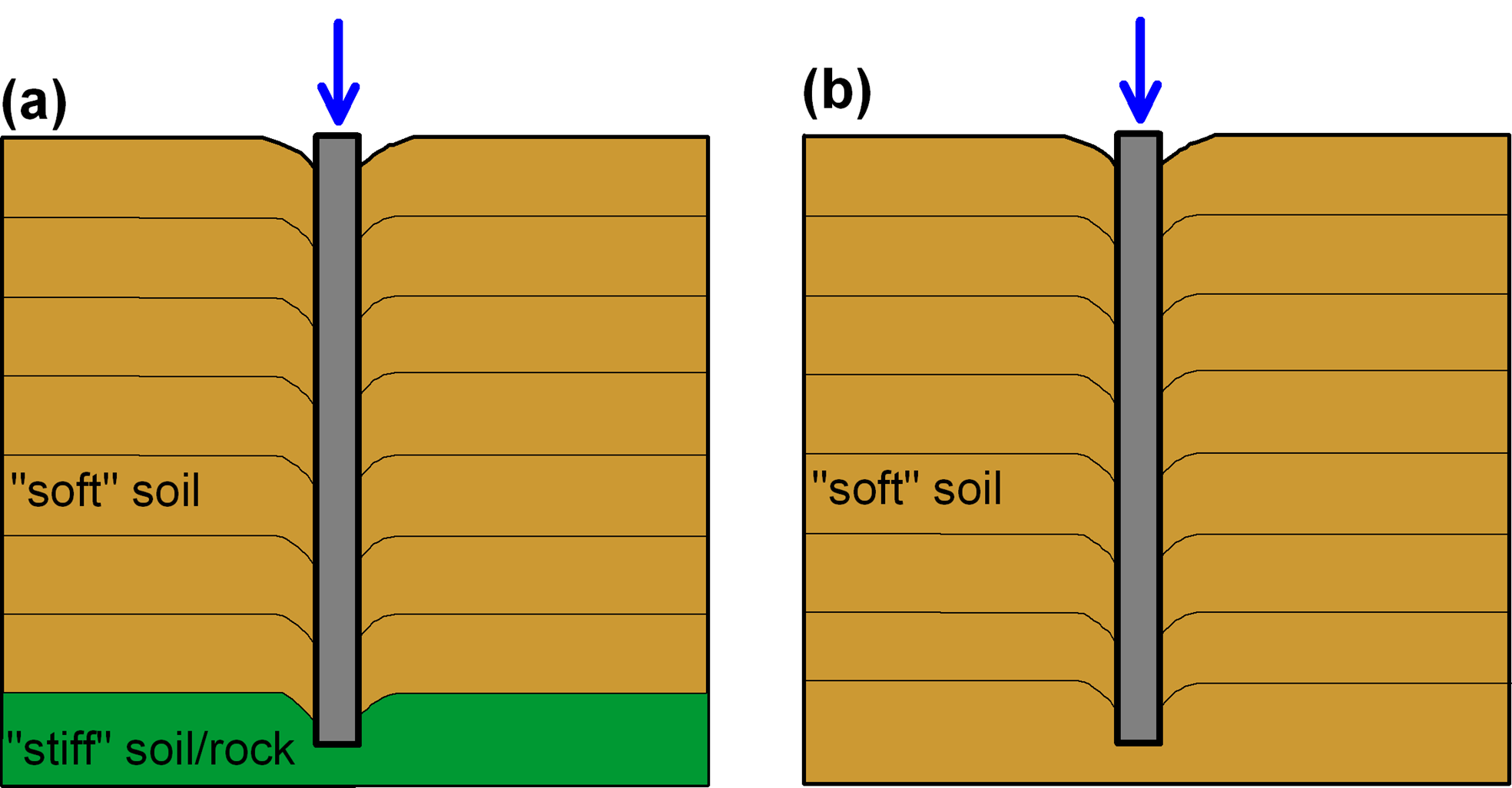
The surficial soil layers may feature low shear strength, or may be too compressible to carry the design vertical compressive load from the structure while satisfying shallow foundation bearing capacity and settlement requirements. Deep foundations are used to transfer the load to a stiff formation encountered at a “reasonable” depth, acting as end-bearing piles (Figure 6.1a). In the absence of a stiff formation at “reasonable” depth, which of course depends on the type of the structure, the load is transferred to the soft soil formation via soil resistance developing along the shaft (friction pile, Figure 6.1b).

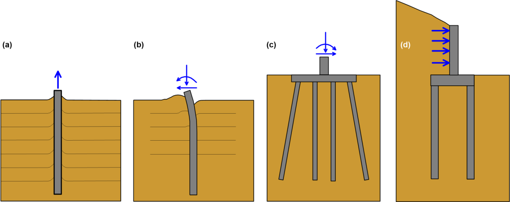
Case 2:
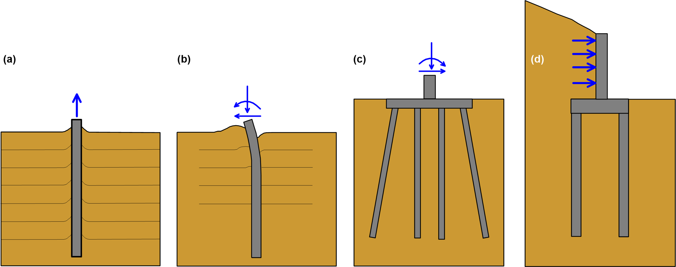
Shallow foundations cannot efficiently transfer high lateral or uplift loads, and bending moments. On the other hand, pile foundations can resist uplift loads through shaft resistance (Figure 6.2a). Lateral loads and bending moments can be transferred by single piles through bending (Figure 6.2b), or by pile groups of vertical or sometimes battered piles, which lateral and bending stiffness is combined when connected with a pile cap (Figure 6.2c). Piles, and especially pile groups, are often used for the foundation of structures transferring significant lateral loads to their foundation, such as tall retaining walls supporting slopes or backfills (Figure 6.2d), highway signs, electricity poles, wind turbines etc.
Case 3:
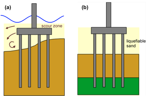
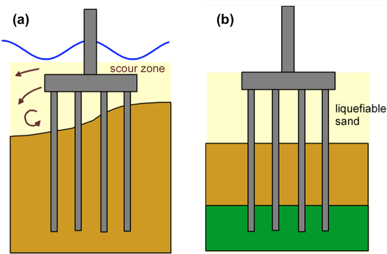
Scour around footings could result in loss of bearing resistance at shallow depths, and the foundation of a bridge pier must extend below the potential scour zone. Guidelines for bridges require that the design of the foundation should not consider the bearing resistance and lateral support above the level of expected scour. In that case, a pile foundation will transfer the loads from the bridge superstructure below the scour zone (Figure 6.3a).
Case 4:
Seismic liquefaction during a strong earthquake may result in sudden loss of the shear strength of loose saturated sands, and flow of the material in areas of non-horizontal ground surface (e.g., riverbanks). Liquefied sands offer significantly reduced support, thus loads must be transferred in deeper, competent layers (Figure 6.3b).
Case 5:
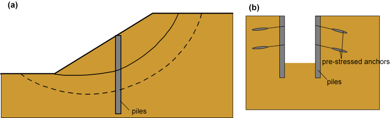
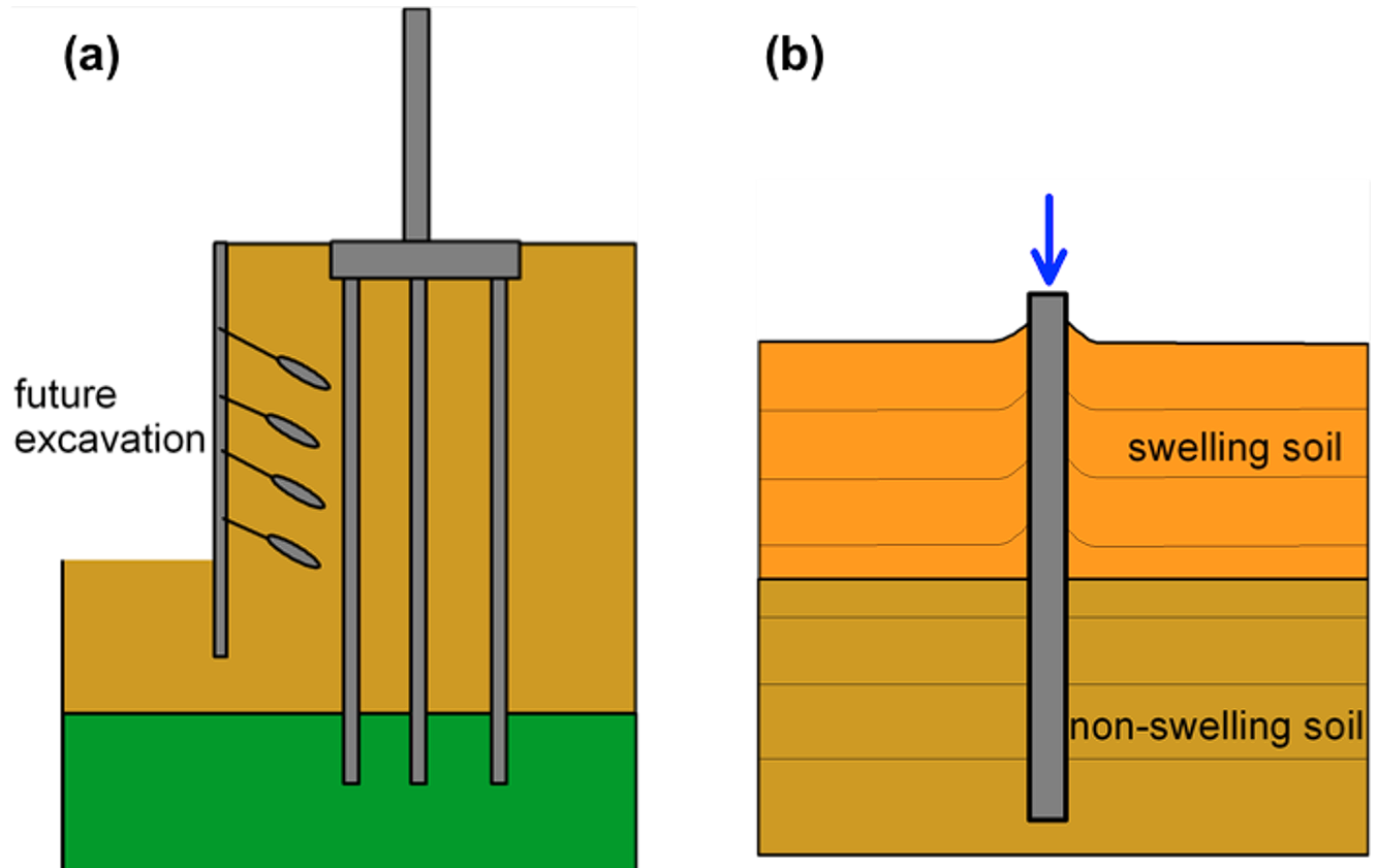
In urban areas, deep foundations may be necessary for supporting structures adjacent to locations where future excavations are planned (Figure 6.4a), to avoid tilt and the requirement for future underpinning.
Case 6:
Pile foundations can be used in areas of expansive soils to resist undesirable seasonal movements. Loads, including uplift and downdrag are transferred to a deeper formation, which is not affected by moisture changes (Figure 6.4b).

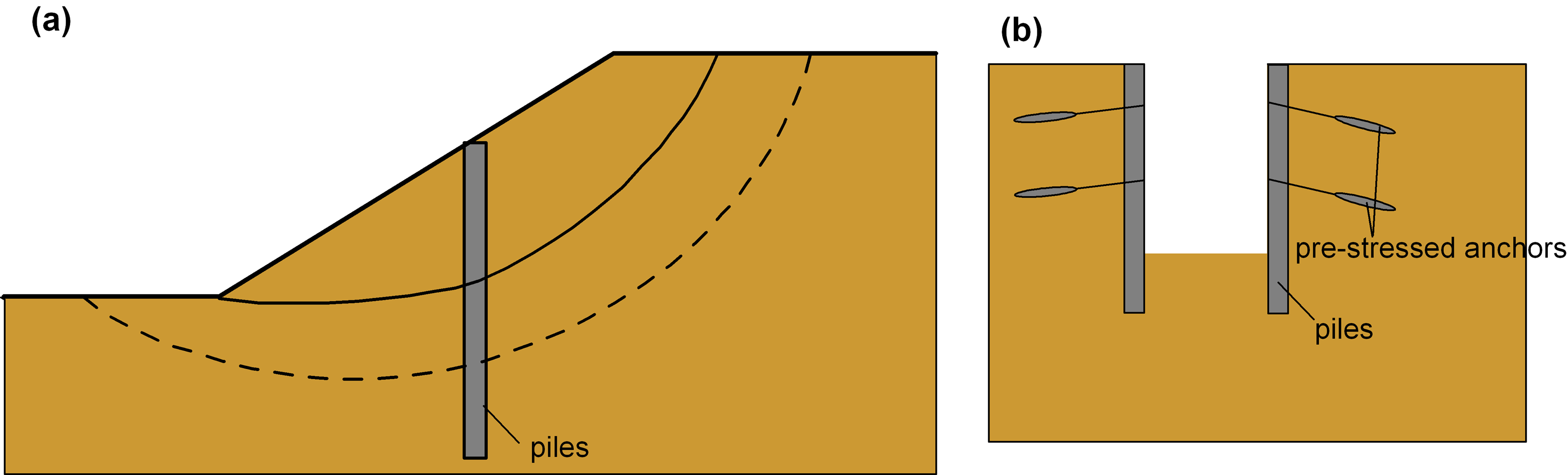
Apart from foundation of structures in the cases described above, piles are also used in a variety of geotechnical engineering applications, such as stabilisation of slopes or active landslide areas, as retaining elements for excavations etc. (Figure 6.5). The same (or similar) analysis methods, design guidelines and construction techniques apply.
