4.11 Additional problems
4.11.1
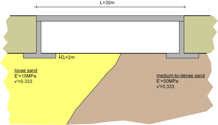
The single-span bridge illustrated in the following figure is going to be founded on shallow square 6 m x 6 m footings, embedded at a depth equal to Df = 2 m. The structural analysis of the bridge resulted in a maximum axial force on the bridge’s piers under serviceability conditions equal to Qw = 10 MN. The site investigation revealed a rather heterogeneous soil profile under the bridge, consisting of loose sand underneath the left abutment, and of medium-to-dense sand underneath the right abutment, featuring the compressibility parameters noted on the figure.
Ignoring the shear resistance developing at the wall-soil interface, calculate: a) the maximum uniform settlement of the critical pier, and b) the angular distortion of the bridge’s foundation. Are these values tolerable, according to Poulos et al. (2001) criteria (Table 4.2)?
Answer:
Critical pier settlement = 0.083 m
Angular distortion Δ/L=0.00193
Allowable total settlement = 100 mm>83 mm OK
Allowable angular distortion = 0.005>0.00193 OK
4.11.2
A wind turbine is going to be founded on the surface (Df = 0) of a deep layer of homogeneous saturated clay, using a single circular footing. Triaxial laboratory tests on specimens of the foundation soil resulted to the following compressibility parameters: E′ = 10 MPa, v′ = 0.333. The maximum axial load on the foundation under serviceability conditions is, according to the Mechanical Engineer, equal to Qw = 5 MN. Determine the minimum radius of the footing, so that its immediate settlement will not exceed 50 mm.
Answer:
R = 3.33 m
4.11.3
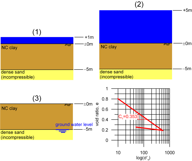
The subsoil at the bottom of a lake consists of a normally consolidated clay layer of thickness 5m, overlaying an incompressible layer of dense sand. Estimate the consolidation settlement of the bottom of the lake:
- Due to an increase of the water level by 4m, and
- Due to a subsequent desiccation of the lake, with the ground water level dropping at the level of the clay-sand interface.
Use the results of the oedometer test shown below, and assume the unit weight of the clay to be γ = 18 kN/m3. For simplicity, do not divide the clay layer into sublayers.
Answer:
- ρpc = 0
- ρpc = 0.33 m
4.11.4
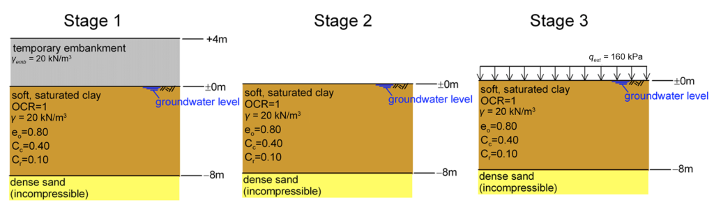
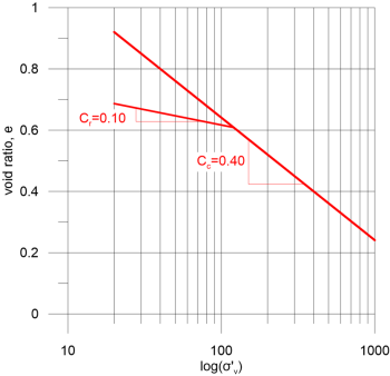
A large cylindrical silo of diameter D = 30 m is going to be founded on a layer of soft saturated, normally consolidated clay of thickness 8 m, overlaying an incompressible layer of dense sand. The contact stress on the foundation of the silo is assumed uniform, and equal to qext = 160 kPa. Preliminary estimates indicated that ground improvement measures must be implemented to increase the bearing capacity of the clay layer, and reduce settlement. The cost-efficient method proposed for the improvement of the clay layer is its preloading via the construction of an extensive temporary embankment. Construction works will be implemented in 3 phases:
- Phase 1: Construction of a temporary embankment at the area of the foundation. The height of the embankment will be 4 m, and the unit weight of the fill material will be γemb = 20 kN/m3.
- Phase 2: Removal of the temporary embankment
- Phase 3: Construction of the silo
Assuming 1-D consolidation conditions, estimate the elevation of the ground surface at the foundation area, at the end of each construction phase. For simplicity, do not divide the clay layer into sublayers.
Answer:
Initial level of ground surface : 0.0 m
At the end of stage 1: -0.848 m
At the end of stage 2: -0.636 m
At the end of stage 3: -1.24 m
