2.8 Contamination control and remediation methods
We use the terms contamination control methods and contamination remediation methods to describe methods for modifying an unacceptable set of environmental conditions, by:
- Removal of a pollutant after the source of pollution has been contained.
- Diversion of groundwater from flowing through a source of pollution, and from contacting a drinking water supply.
- Lowering the groundwater table below a source of pollution to prevent its contamination.
Different methods apply for groundwater and soil contamination. Groundwater control and remediation methods are based on the following general concepts:
- Extraction of groundwater from (or injection of fresh water into) wells or drains, to capture a pollutant or alter the direction of groundwater movement.
- Installation of gravity collection systems such as subsurface drains, designed to intercept groundwater.
- Construction of low hydraulic conductivity barriers, which consist of a vertical wall of low hydraulic conductivity materials build to divert groundwater flow.
- Biological or chemical in situ treatment methods.
Contaminated soil control and remediation methods on the other hand are based on:
- Disintegration of organic pollutants by microorganisms (bio-remediation). This method can, under some circumstances, be used for contaminated groundwater too.
- Chemical extraction of pollutants via soil washing.
- Thermal treatment of contaminated soil in situ or in a special furnace.
- Extraction of contaminants, with the vacuum method, or simply:
- Excavation and removal of contaminated soil, where the soil is moved to an appropriate repository. The cost of this method can be extremely high and the problem is not solved, just transferred elsewhere.
Some details on the most common methods used for contaminated groundwater and soil control and remediation are provided in the following sections.
2.8.1. Groundwater contamination control and remediation methods
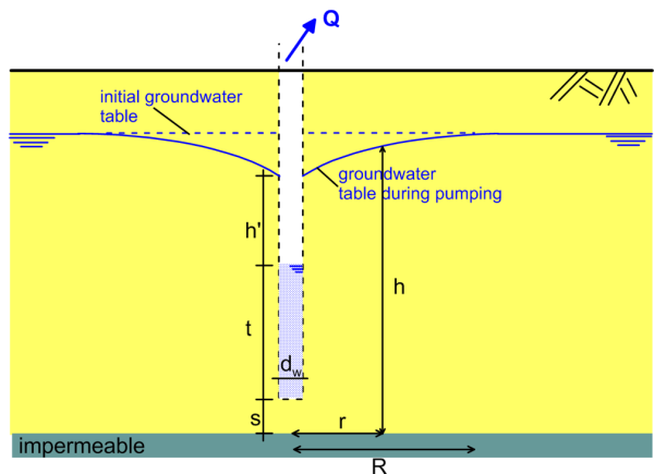
One of the most widely used methods for groundwater treatment is the groundwater pumping or “pump-and-treat” method. When pumping from a well begins, the head in the well is lowered below the free-field level ho in the surrounding aquifer (Figure 2.15). As a result, water will flow from the aquifer into the well, and the initial groundwater table is depressed, forming a depression cone. The surface of the cone is called draw-down curve, and the outer limit corresponds to the radius of influence R (Figures 2.15 and 2.16). Assuming that Darcy’s law is valid, axisymmetric conditions and a simplified soil stratigraphy, we can estimate the flow from the well Q as:
(2.9) 
where the area depends on the thickness of the aquifer, and q is the Darcy’s water flux (Figure 2.15):
(2.10) 
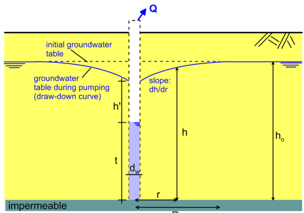
Adopting some further simplifying assumptions, such as a well penetrating down to the level of the aquitard (Figure 2.15) and an infinitely extending pervious stratum, we can estimate the draw-down curve geometry (and thus design the dewatering system) as:
(2.11) 
where R is the radius of influence, that depends on the boundary conditions of the problem, ho is the original elevation of the groundwater table, and Q is the pumping rate.
The above formulas are based on certain important simplifying assumptions, such as uniform soil and axisymmetric flow towards a single well. Numerical methods can be used for the design of a dewatering system in case where the conditions in situ do not match the mentioned assumptions, and this is demonstrated later in Part 2.
Groundwater pumping for contamination control can be used for:
- Lowering groundwater level in the vicinity of polluted sites.
- Increasing the separation between pollutants and groundwater.
- Supplementing a barrier system.
- Extract contaminated water for treatment.
Note that groundwater pumping and water table lowering can result in subsidence, due to the increase in soil effective stresses. Injection wells or recharge basins may need to be used in conjunction with the pumping wells to recharge the aquifer, and avoid affecting nearby structures.
Subsurface gravity drains can be used to:
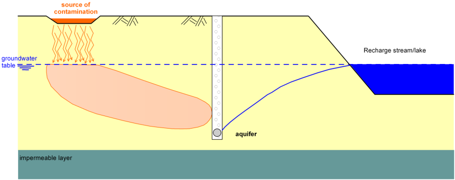
- Reduce the flow from non-contaminated sources, such as a nearby stream or lake, thus reducing the amount of groundwater that must be collected through pumping for treatment (Figure 2.17).
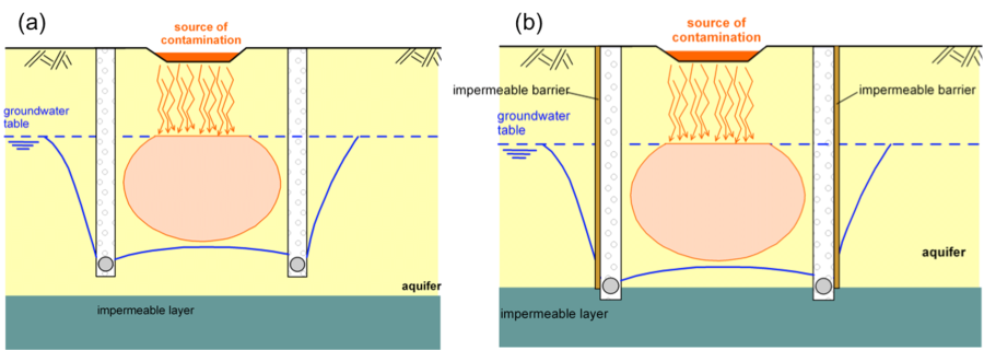
- Lower the groundwater out of contact with a contaminated zone (Figure 2.18a).
- Used in conjunction with impermeable barriers, can completely isolate a contaminated zone (Figure 2.18b).
Drains must be filled with filter coarse-grained material of proper gradation, and wrapped with geotextiles to avoid clogging (Figure 2.19). A pump can be used to remove groundwater from the pipes installed at the bottom of the drains.
Low hydraulic conductivity, practically impermeable, barriers are constructed to block the flow of groundwater, and thus prevent advection of the pollutant (Figure 2.20). For that, they should feature permeability of the order of 10-8 to 10-9 m/sec, or lower. Methods for constructing low hydraulic conductivity barriers include:
- Slurry walls, made of soil-bentonite of cement-bentonite mixes using special machinery (slurry wall hydraulic grab).
- Grouting curtains.
- Sheet piles.
- Ground freezing.
- Electrokinetic barriers.
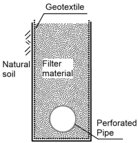
Figure 2.19. Filling of drains with coarse-grained filter material to avoid clogging. 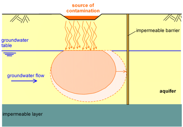
Figure 2.20. Use of impermeable barriers to prevent advection of the pollutant.
Barriers alone will not remove the pollutant of course, but they can be used in conjunction with pumping or drains as illustrated in Figure 2.18b. The design of such a system with the aid of numerical methods is discussed at the end of this Part. Note that long-term performance of barriers is rather questionable, and if the barrier begins to leak, further remedial measures must be implemented; an extremely expensive task if the area has been redeveloped.
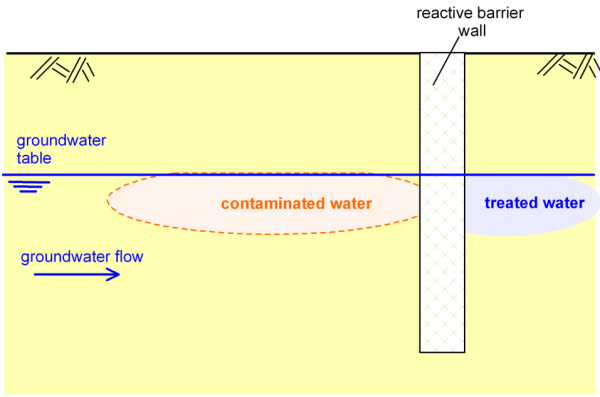
Reactive barriers on the other hand can be used for the in situ treatment of polluted water, as it moves through an aquifer under natural hydraulic gradient (Figure 2.21). A portion of the aquifer is excavated, and subsequently backfilled with a porous reactive mixture. Reactive barriers are installed downstream of the contamination source, and the natural groundwater flow carries the polluted water through the barrier, thus costs related to pumping the contaminated water on the surface are minimised.
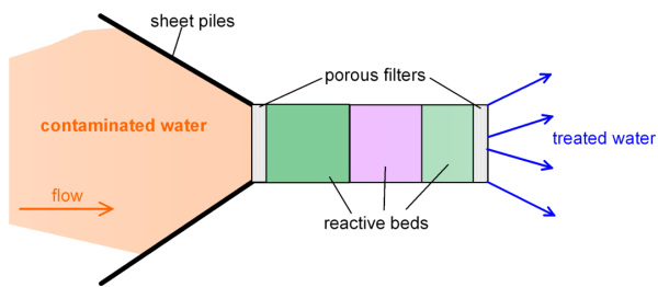
Depending on the type of pollutants, different materials are used to backfill the reactive barrier. For example, mixtures of zero-valence metals, such as zero-valence iron mixed with clean sand can be used for the degradation of chlorinated organic compounds or hexavalent chromium. In practice, a funnel-and-gate system (Figure 2.22) is used to “drive” the contaminated water through the reactive beds with the aid of sheet piles, which also serve as temporary retaining measures for the excavation of the aquifer material.
2.8.2. Soil contamination control and remediation methods
Bio-remediation, one of the most common methods for treating contaminated soils but also groundwater, is based on the concept of biodegrading organic pollutants via introducing microorganisms that can metabolise the pollutants into non-toxic products.
The method has been used for decades in urban sewage treatment facilities. In recent times it is being also used to treat soils contaminated by polycyclic aromatic hydrocarbons (PAH), volatile organic compounds (such as BTEX, a mixture of benzene, toluene and xylene) and phenolic or nitroaromatic compounds. Microorganisms such as bacteria or fungi can metabolise these organic compounds, and grow using the carbon and/or energy produced. The final products of this process are inorganic compounds such as carbon dioxide and water, or other less harmful organic compounds, such as methane or sulphide. For the successful implementation of bio-remediation, certain conditions must be met:
- Appropriate microorganisms that can metabolise the specific pollutants must be introduced.
- Nutrients such as nitrogen, potassium and phosphorus are necessary for growth of the microorganisms, and must be available in the subsoil.
- Soil conditions i.e., temperature, humidity and pH must favour the development of microorganisms.
Given the above, a pilot application is highly recommended, to ensure effectiveness and optimise the procedure. Bio-remediation is a slow process that can take up to 20-30 years in some cases. It is more effective in coarse-grained, non-saturated soils, where oxygen is available and the metabolism is aerobic. Certain techniques such as soil venting via stirring can enhance the process.
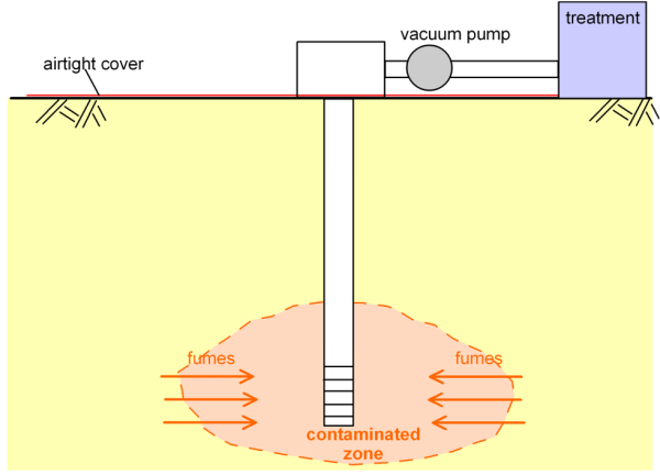
The vacuum extraction method is used to remove volatile hydrocarbons from the vadose zone. A well is bored, and suction is applied to collect the hydrocarbons. The method is applicable to high-permeability soils, where the effective radius of each well is larger. The vadose zone must not be in contact with the air, thus it is necessary to cover the ground surface with an airtight material, to increase the effectiveness of the method (Figure 2.23).
Soil washing involves injecting a mixture of water and acids or detergents into the soil under high pressure, while stirring the soil to remove the pollutants. The main drawback of soil washing is that it requires significant amounts of water, which after the application of the method will contain a significant amount of pollutants. Thus the water used for washing must be treated too, before being recycled. Care must be taken so that the washing water does not infiltrate to contaminate lower aquifers.
Finally, thermal treatment is used to remove volatile pollutants such as oil products, cyanides, polycyclic aromatic compounds, asbestos etc. by heating them beyond the boiling point of the hazardous compound. Special control procedures must be implemented while applying this method, as toxic gases produced during heating under high temperatures may be released in the environment.
