1.9 The Vane Shear test
The vane shear test is performed to measure in situ the undrained shear strength Su of soft-to-medium clays with undrained shear strength less than 50 kPa.
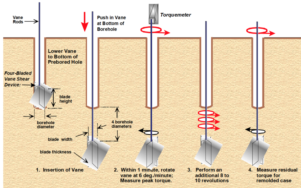
The standard procedure for field vane shear tests is described in AS 1289.6.2.1 (Figure 1.35): A four-blade vane is pushed into the soil, at a depth no closer than four borehole diameters from the immediately above test location, and it is rotated until the soil shears to failure, while measuring the maximum torque T necessary to rotate the vane. The standard dimensions of the vane are 130 mm height (H) x 65 mm diameter (D) x 3 mm thickness (t). Both the peak shear strength and the remolded shear strength are measured: the former during the rotation of the vane for 1 minute at a constant rate of 6 deg/min, and the latter from the constant torque measured after 8-10 additional rapid revolutions. The sensitivity St of the clay is also estimated, as the ratio of the undisturbed peak undrained shear strength to the remolded undrained shear strength (see Section 1.8.3).
The undrained shear strength is estimated from the measurements obtained during the vane test as:
(1.34) 
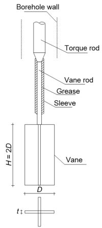
The above Eq. 1.34 is valid for standard vanes, where H = 2D (Figure 1.36). Note that the skin friction of the vane rod should be accounted for in the calculation of the maximum torque, T.
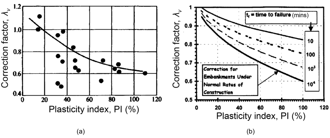
Based on experience from failures of embankments on soft clay immediately after construction, it is acknowledged that the shear vane test tends to overestimate the undrained shear strength. This is due to the fact that clays exhibit viscous behaviour, which suggests that their strength depends on the rate of shearing: the higher the rate, the higher the strength. Therefore a reduction factor λv needs to be considered when estimating the design undrained shear strength (corresponding to time to failure of the order of days/weeks) from vane tests where failure takes place within 1-2 mins:
(1.35) 
This reduction factor depends on the plasticity index PI of the clay (Figure 1.37), as the higher the plasticity index (increased clay content), the more prominent viscous effects are.
The advantage of the vane shear over other in situ testing methods for determining the undrained shear strength (CPTu, Eq. 1.16) is that the interpretation of the former is generally not sensitive to uncertainties regarding the shape of the failure surface (or value of the cone factor Nkt). It is widely accepted that rotation of a four-blade vane into soft soil will result in a cylindrical failure surface, and this is reflected in Eq. 1.34. Therefore, it is quite common to use vane shear tests to obtain site-specific cone factor values, in other words to calibrate the interpretation of cone test results on vane shear tests. Finally, it must be noted that the undrained shear strength measured by means of vane shear tests is the undrained strength under simple shear conditions (see Kouretzis et al. 2017), which in not equal to the undrained shear strength measured during common triaxial compression tests, as the stress path to failure is different. The implications of this when it comes to stability calculations are discussed in Part 5.
