1.4 Boreholes and sampling methods
Sampling boreholes are a critical part of any geotechnical investigation campaign. They are performed to:
- Identify the distribution of geomaterials with distinctive properties into the subsoil, including the presence and thickness of layers.
- Retrieve samples for laboratory tests.
- Determine the depth of the groundwater table, through installation of piezometers.
- Provide access for the introduction of in-situ testing devices.
| (Geo)structure type | Minimum number of sampling boreholes | Minimum depth of sampling boreholes |
|---|---|---|
| Structural foundations | One per substructure unit for width ≤ 30 m | Advance boreholes: (1) Through unsuitable foundations soils e.g., peat, highly organic soils, soft fine-grained soils, uncontrolled fills into competent material of suitable bearing capacity (2) to a depth where stress increase due to external footing loading is less than 10% of existing effective vertical stress (see Part 3) or (3) a minimum of 3 m into bedrock, if bedrock is encountered at shallower depth |
| Retaining systems | Two per substructure unit for width > 30 m. Boreholes should be alternatively spaced every 30 m to 60 m in front of and behind wall | Advance boreholes to a depth of time times the retained height, or a minimum of 3 m into bedrock |
| Culverts | Two boreholes, depending on length | See structural foundations |
| Bridge approach embankments founded on soft soils | One borehole at each embankment location, to address issues associated with stability, settlement, negative skin friction, lateral pressure on bridge pile foundations. | See structural foundations. Additional shallow boreholes (trial pits) are an economical means to determine depth of unsuitable surface foundation soils |
| Earthworks (cuts and embankments) | One borehole every 60 m (erratic conditions) to 150 m (uniform conditions). For high cuts and fills (e.g. 10 m), two boreholes along a straight line perpendicular to centerline or planned slope face, to establish an appropriate cross-section for stability analysis | Cuts: (1) In stable materials, advance boreholes a minimum of 3 to 5 m below cut grade. (2) In soft/problematic soils, advance boreholes below cut grade to firm materials, or to the height of the cut below grade, whichever occurs first. Embankment: Advance boreholes to firm material, or to depth twice the embankment height, whichever occurs first |
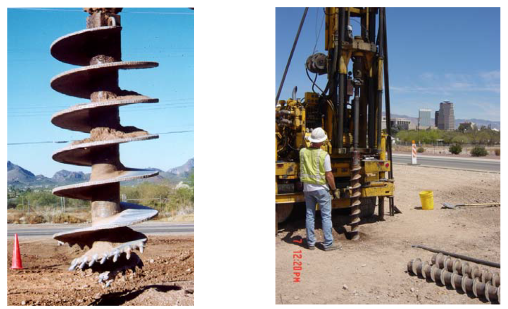
Many types of equipment and soil boring techniques are used in practice, and describing them in detail is beyond the scope of this Part. Only an overview of most common methods is provided in the following. Auger borings are commonly used for boring through soil formations (Day 1999, FHWA 2006). An auger is an apparatus with a helical shaft that is manually or, most commonly, mechanically advanced to drill a hole into soil by applying downwards pressure. The auger may be continuous, where the helix extends along the entire length of the shaft, or for shallow boreholes, discontinuous (single flight) where the auger helix is at the bottom of the drill stem (Figure 1.4).
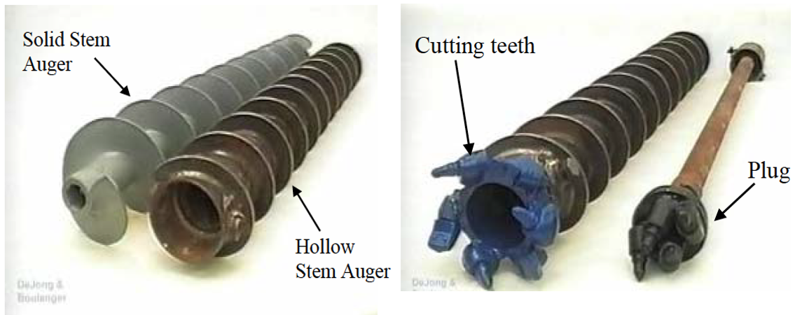
There are two types of continuous flight augers: solid stem and hollow stem (Figure 1.5). The solid stem must be periodically removed from the borehole to allow retrieving soil samples. A hollow stem auger has a circular hollow core that allows for sampling through the center of the auger, which acts like casing to facilitate sampling in loose/soft soils under the groundwater table.
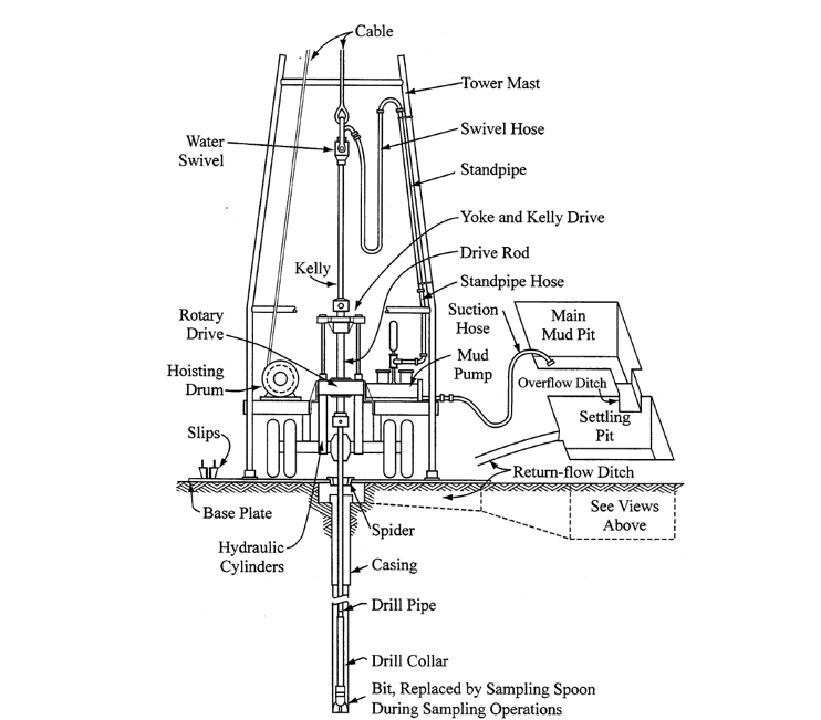
If relatively stiff/hard formations are encountered, a water-circulation system is used, that aids cutting and drawing the material to the surface (wash boring-Figure 1.6). Casings are often used to prevent cave-in of the borehole. Casing of the borehole may require additional time and effort, but will result in a protected borehole, where monitoring instruments can be installed e.g., a piezometer to measure groundwater table level fluctuations, or an inclinometer for measure possible lateral soil movements.
When drilling through generally stiff formations, rotary coring is used (Figure 1.7) to retrieve intact core samples. Power rotation of the drilling bit is accompanied by the introduction of a circulating fluid to remove cuttings from the hole.
Besides the methods described above, which are the ones typically used in practice, a plethora of other methods are also used for boring through soils and rocks e.g. bucket auger boring, Becker hammer penetration, percussion drilling, sonic drilling etc.
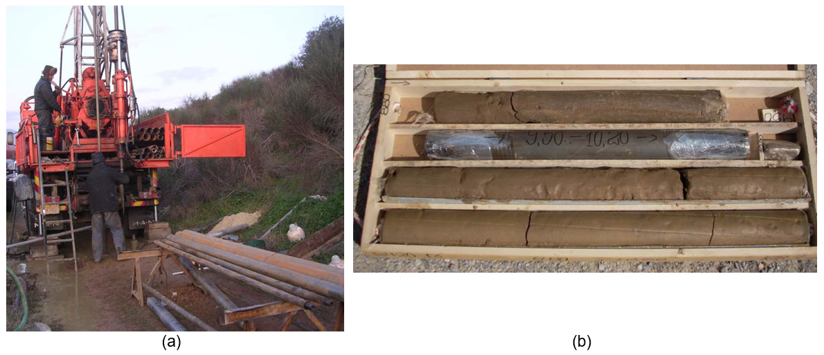
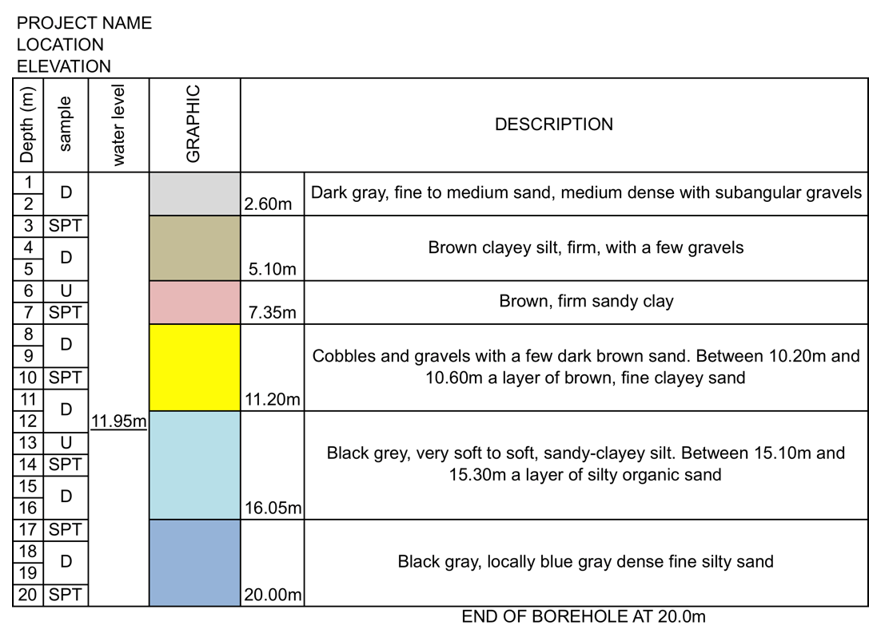
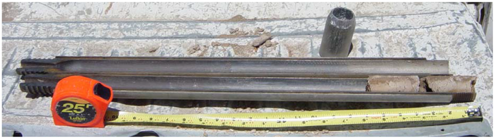
When the borehole core is retrieved to surface (Figure 1.7b), a qualified person e.g., a geologist should observe the type, texture and color of the soil retrieved from different depths, and fill in a borehole log with all the information (Figure 1.8).
As far as the method used to retrieve soil samples to the surface is concerned, there are two main categories of soil sampling techniques: disturbed sampling and undisturbed sampling.
Disturbed sampling of soil provides the means to evaluate soil stratigraphy by visual examination, and soil specimens for laboratory index determination or testing of remolded samples. Disturbed samples are usually collected using split-barrel samplers (Figure 1.9). Shallow disturbed samples can be also obtained by using hand augers or from test pits.
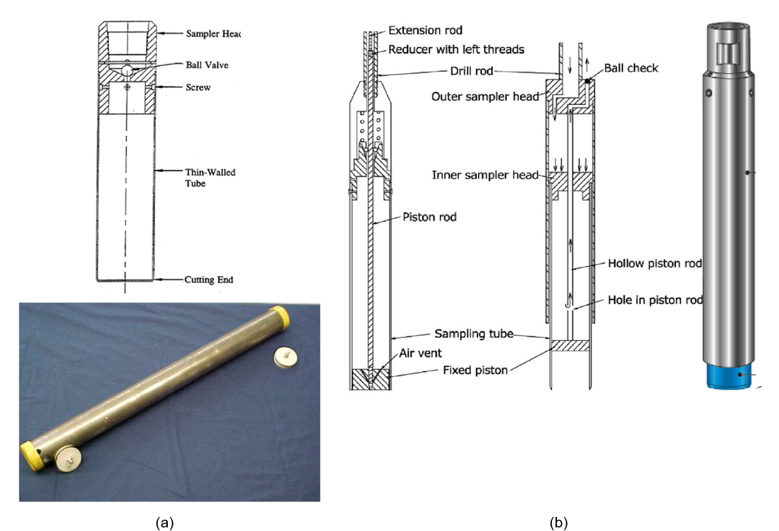
Undisturbed, high-quality, soil samples on the other hand are required for performing laboratory shear strength and consolidation tests on soft to stiff fine-grained soils. In reality, it is impossible to collect truly undisturbed soil samples, as soil stress changes upon sampling and retrieving the sample to surface. The goal of undisturbed sampling is to minimise alteration of the soil structure, changes in the moisture content or the void ratio, and changes in the chemical composition of the soil. Various methods are used for undisturbed soil sampling, ranging from simple cost-effecting methods (which however induce significant disturbance during sampling), as the thin-walled Shelby tube (Figure 1.10a), up to extremely costly methods (e.g. soil freezing) used only in special projects.
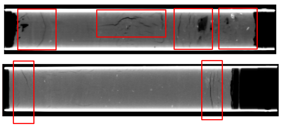
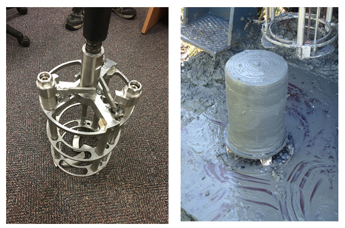
As illustrated in Figure 1.11 thought, sampling even with the more advanced fixed-piston sampler (Figure 1.10b) with diameter 50 mm to 100 mm will result in some soil disturbance, particularly at the top and bottom parts of the sample. As the soil fabric is disturbed, laboratory test results may be compromised, and this must be properly considered when interpreting laboratory test results to retrieve soil parameters. More advanced sampling tools, such as mini-block sampler used in the University of Newcastle (Figure 1.12) will produce soil samples of optimum quality for laboratory testing.