1.11 Geophysical methods for soil exploration
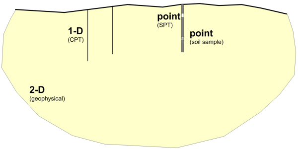
Non-destructive methods, where the term non-destructive suggests that no sampling, boring, or excavating of soil is involved, are also used to provide information on soil and rock properties, hydrogeological conditions, the subsoil profile etc. Information obtained through geophysical methods is generally two- (or three-) dimensional (spatial), compared to one-dimensional or point information provided by boreholes/CPT soundings or soil samples, respectively (Figure 1.40).
The main advantage of geophysical methods is exactly their ability to provide spatial information on subsoil stratigraphy and groundwater levels, covering effectively a wide area. Geophysical methods are relatively quick and inexpensive, but their results are mainly qualitative, so they have limited applicability for deriving design geotechnical parameters. However, they can be implemented during early stages of a project, to better plan a detailed site investigation. Note that covering a wide area with geophysical methods requires real estate, to conduct tests properly.
The most common methods mentioned in AS1726 are described compendiously in the following paragraphs, as it is not within the scope of this Part to discuss the interpretation of geophysical tests.
1.11.1. Seismic surveys
Seismic surveying methods, such as Multichannel Analysis of Surface Waves (MASW) is based on the principle that waves travel within the earth crust at different velocities, which depend only on the geomaterial properties. For example, common shear waves propagate with a wave velocity VS that is equal to:
(1.37) 
where G0 is the elastic small-strain shear modulus of the soil or rock layer, and ρ is its mass density. This implies that if we can measure the shear wave velocity, we can find the small-strain compressibility parameters of the specific material.
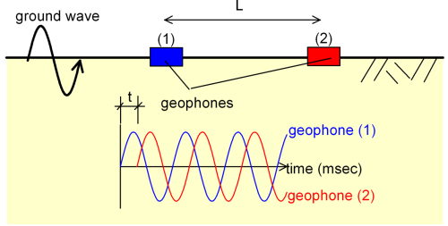
Measuring of the seismic velocity is possible by using geophones, which are motion-sensitive instruments that convert ground motion to electrical signals. This can be accomplished by generating a ground wave, simply by pounding a sledgehammer on the ground surface or by using a small amount of explosives. With geophones, we can measure the difference in the arrival time of the wave, t at two geophones spaced L meters apart. The propagation velocity of the wave is equal to V = L/t (Figure 1.41).
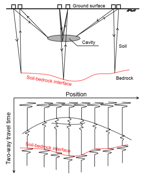
In real soils however, this procedure is more complicated, since when a wave encounters an interface between two soil/rock layers with different properties, and thus different wave propagation velocities, secondary waves are generated due to reflection, refraction and diffraction (Figure 1.42). However, we can take advantage of these secondary waves to determine not only the properties of the subsoil layers, but also the stratigraphy, with methods such as the seismic refraction method or the Multi-Channel Analysis of Surface Waves (MASW) method.
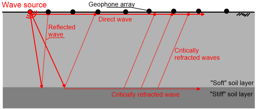
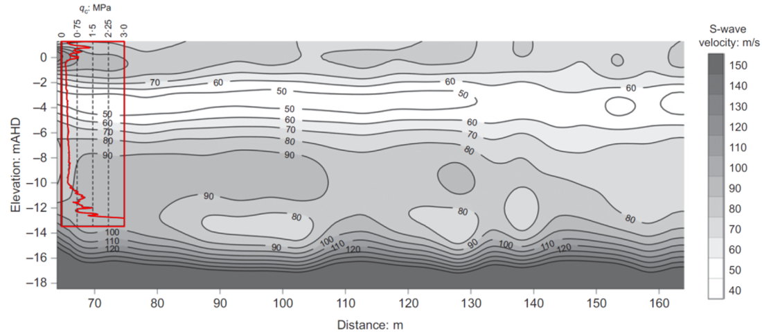
Employing the same principles, interpretation of multiple geophone recordings can provide information about subsoil stratigraphy (Figure 1.43). The seismic refraction method is mainly applied for determining the depth of a major refractor e.g., the bedrock, which has a wave propagation velocity significantly higher than the above softer formation. Other applications of the method include locating weathered fault zones, thickness of aquifer layers etc.
1.11.2. Electrical resistivity method
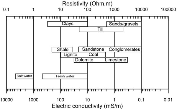
The electrical resistivity method is used for determining the groundwater table level, the location of any possible subsoil cavities, the identification of the extent of fault zones etc. The concept on which the method is based consists of measuring the electrical potential difference (AC voltage) on the ground surface, created by an AC current. The potential difference reflects the “resistance” to the flow of the electric current through the soil, which is correlated to the soil’s electrical resistivity. Soil resistivity varies with the water content: the pore fluid provides the only electrical path in sands, while both the pore fluid and the surface charged particles provide electrical paths in clays. So, differences in resistivity can be interpreted as differences in soil stratigraphy (Figure 1.44).
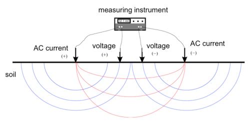
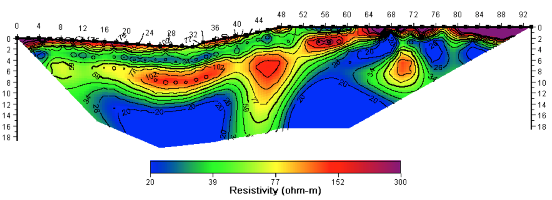
Application of this method involves placing four electrodes on the ground surface, applying an AC current to the outer two electrodes, and measuring the AC voltage between the two inner electrodes (Figure 1.45). The spacing of the electrodes is related to the depth of the investigation: the greater the spacing, the larger the depth where we can get information from. A subsurface resistivity profile is created by performing successive measurements at different spacing (Figure 1.46).
1.11.3. Ground penetration radar (GPR)
Ground penetration radar (or georadar) is based on the same principles as the radar used in aviation. An antenna is used to transmit and recover high frequency (10MHz to 1000 Mhz) electromagnetic pulses originating from a pulse generator. When the wave hits a buried object or a boundary with different dielectric constants, the reflected return signal is altered (Figure 1.47, Davis and Annan 1989). The method is practically based on the same concept as seismic surveys, only in this case electromagnetic waves are used.
GPR has many engineering applications in general. Its key applications in Geotechnical Engineering include identifying the location of buried objects (utility lines) or cavities, and soil profiling.