4.3 Tolerable settlement
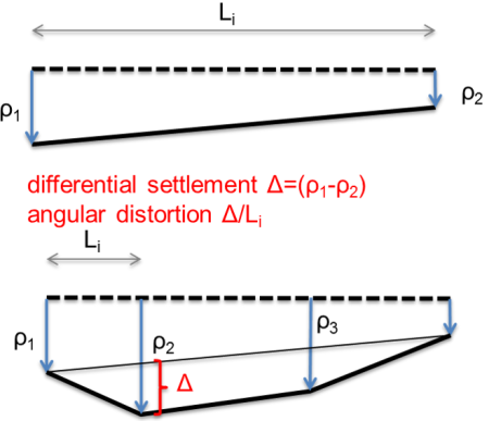
As discussed above, limits on uniform settlement are usually associated to the function of the building e.g., access, connection to services etc. Limits on differential settlement (or differential deflection) and angular distortion, which are defined in Figure 4.6, depend on the type of the structure, and on the properties of the load-bearing frame. Building codes and standards, such as AS2870, impose limits on the maximum differential settlement to prevent e.g., cracks in masonry walls. Such limits for residential slabs and footings are presented in Table 4.1. Poulos et al. (2001) summarise typical limit values of uniform settlement, angular distortion, tilt and deflection for various types of structures. These limits are presented in Table 4.2. Of course other, perhaps stricter, project-specific limits may apply.
| Structure type | Maximum allowable differential settlement (differential deflection), as function of span length, L | Maximum allowable differential settlement (differential deflection), (units: mm) |
|---|---|---|
| Clad frame | L/300 | 40 |
| Articulated masonry veneer | L/400 | 30 |
| Masonry veneer | L/600 | 20 |
| Articulated full masonry | L/800 | 15 |
| Full masonry | L/2000 | 10 |
| Structure type | Criterion | Limitation | Recommended value |
|---|---|---|---|
| Common framed buildings and reinforced load-bearing walls | Structural damage | Angular distortion | 1/150 to 1/250 |
| Cracking in walls and partitions | Angular distortion | 1/500; 1/1000 to 1/1400 for end bays | |
| Visual appearance | Tilt | 1/300 | |
| Connection to services | Total settlement | 50 to 75 mm for coarse-grained foundation soil; 50 to 135 mm for fine-grained foundation soil | |
| Tall buildings | Operation of lifts | Tilt | 1/1200 to 1/2000 |
| Unreinforced load-bearing structural elements (e.g., masonry) | Cracking by relative sag | Deflection ratio (maximum relative deflection in a panel/panel length) | 1/2500 for wall length/height ratio = 1; 1/1250 for wall length/height ratio = 5 |
| Cracking by relative hog | Deflection ratio (maximum relative deflection in a panel/panel length) | 1/5000 for wall length/height ratio = 1; 1/2500 for wall length/height ratio = 5 | |
| Bridges | Ride quality | Total settlement | 100 mm |
| Function | Horizontal movement | 38 mm | |
| Structural damage | Angular distortion | 1/250 for multispan bridges; 1/200 for single span bridges |
