Example 6.15
Analysis of a concrete pile embedded in layered soil with the beam-on-nonlinear Winkler spring method for lateral loading
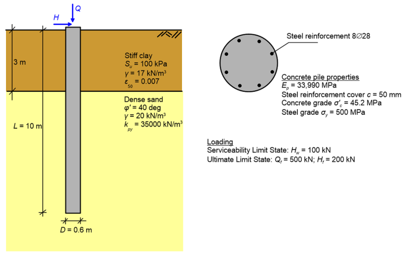
A single concrete free-head pile of diameter D = 0.6 m and length L = 10 m is embedded in a layered soil profile consisting of a stiff clay layer, underlain by dense sand. The soil layers are featuring the properties shown in the Figure below, while the water table is found below the pile toe. Determine: i) The variation of lateral pile deflection with depth, if a serviceability lateral load Hw = 100 kN is applied on the pile’s head; ii) The variation of bending moment and shear forces along the pile, if a ultimate limit state lateral load Hf = 200 kN is applied on the pile’s head; iii) Whether the pile has sufficient structural capacity to carry the developing internal forces due to the ultimate limit state lateral load, if the ultimate limit state axial force acting on the pile is Qf = 500 kN.
Answer:
To answer these questions, we must analyse the pile using the Finite Element Method, since the pile is embedded in layered soil (and the thickness of the surficial stiff clay layer 5D is less that the critical pile length, see Figure 6.110). We have sufficient information to determine the p–y curves along the length of the pile, following the steps described in Chapter 6.27 for piles in stiff clay without the presence of free groundwater (top 3 m of the pile) and for piles in sand (bottom 7 m of the pile). Thus we can set up a beam-on-nonlinear Winkler spring Finite Element model. The results presented in the following have been obtained with an in-house Finite Element code (Elphick 2014). Appropriate boundary conditions were set to account for the fact that the pile’s head is free to rotate (hence the moment at the pile’s head will be zero). Keep in mind that, according to the described earlier in Chapter 6.27, pile response to lateral loadings is assumed independent on the axial compressive load applied on its head. However, the maximum bending moment that the concrete pile’s section can carry depends on the compressive load, since the pile is made of reinforced concrete. Hence the ultimate limit state axial force acting on the pile Qf is provided.
Figure 6.123 below presents the variation of lateral pile deflection with depth for lateral load Hw = 100 kN and the bending moment and shear force diagrams for lateral load Hf = 200 kN. Note that the code will return an error if the ultimate soil reaction is reached along the entire length of the pile i.e., if the pile fails with a short pile failure mode. As discussed earlier, designing a pile to fail with a “brittle” short pile failure mode is not recommended.
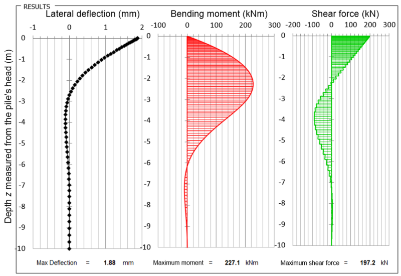
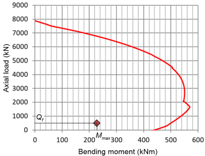
However, from the results presented above we cannot conclude whether the pile can safely transfer the ultimate limit state load to the subsoil, because we do not know whether its cross-section can carry the maximum moment (Mmax = 227.1 kNm) without failure. For that we need to plot the strength interaction diagram of the pile’s section, which depends on the properties of the pile (number and diameter of reinforcement bars, concrete and steel grade etc.). The strength interaction diagram is shown in Figure 6.124 where, for simplicity, we have assumed that the axial compressive load acting at the pile’s head Qf is constant along the pile’s length. In reality the axial load will be reduced by the shaft friction resistance that will develop along a length of about z = 2.3 m i.e., the elevation where Mmax develops on the pile. It is clear from Figure 6.124 that the Qf – Mmax combination calculated during the Ultimate Limit State stage of the analysis falls within the safe region of the strength interaction diagram, therefore the pile can safely carry the applied lateral loading.
Finally, note that we have not applied any geotechnical reduction factors in this analysis. To do so, and thus comply with AS2159, we should divide the Ultimate Limit State lateral load and axial force with an appropriate value of φgb as well as use characteristic values of the soil parameters in the analysis. In addition, appropriate factors must be applied for the determination of the strength interaction diagram of the pile’s section, according to the pertinent concrete design standard (AS3600).
