Example 5.1
Design of a circular footing according to AS5100.3 with analytical methods
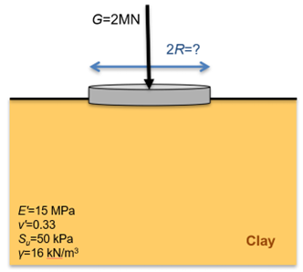
A wind turbine is going to be founded on a shallow circular footing, on the surface of a saturated clay layer of practically infinite thickness, with the geotechnical properties shown in the figure below. The undrained shear strength of the clay has been determined from an adequate number of triaxial laboratory tests on undisturbed samples. Determine the minimum radius of the footing required to satisfy Ultimate Limit State requirements of AS5100.3. Assume that the footing is rigid and rough, and that imposed (live) loads are negligible.
Answer:
The bearing capacity of a circular footing resting on a saturated clay layer under short-term, undrained loading conditions can be determined analytically, by assuming rigid plastic response of the soil. Derivation of the exact solution is provided elsewhere, while some fundamentals are discussed in Chapter 5.3. The ultimate geotechnical strength in terms of stress (bearing capacity), qf is:


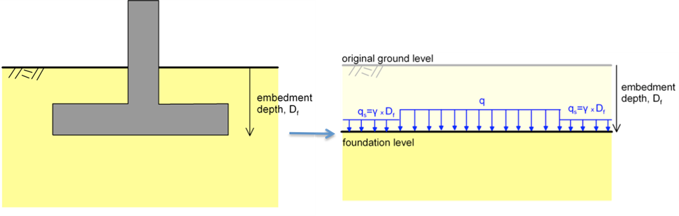
where Su is the undrained shear strength of the clay layer, and qs is the weight of the soil excavated to embed the footing qs = γDf (Figure 5.14). In the case at hand, where the footing rests on the top of the soil surface, it is qs = 0. The other term in the above equations (e.g., 5.14Su) represents the bearing capacity in terms of stress of a footing resting on the soil surface and Ncu = 5.14 is the so-called bearing capacity factor for undrained loading, that depends on the shape of the footing, and on the soil-footing interface properties.
The design action load S* for a load combination considering permanent action only is (AS1170.0):

The bearing of a rough circular footing on the ground surface, in terms of stress, is:

Remember that the undrained shear strength to be used for the estimation of the ultimate geotechnical strength is always the characteristic value. Converting stress to force provides the collapse load Qf:

As the characteristic value of the undrained shear strength has been determined from laboratory tests on undistrurbed samples, the appropriate range of the geotechnical strength reduction factor φg from Table 5.1 is φg = 0.45 to 0.60. Selecting conservatively the lower bound of the proposed range, Eq. 5.2 that provides the design capacity becomes:


