6.16 Static pile load tests
6.16.1 General
Static load testing is a “direct” method for determining the ultimate geotechnical strength of piles. A pile load test is practically a full-scale experiment to determine the load-settlement (or load-uplift, for tension tests) curve of an actual pile installed in the project site, in order to verify the design capacity and predicted pile settlements, or to optimise the design of the rest of the piles to be constructed.
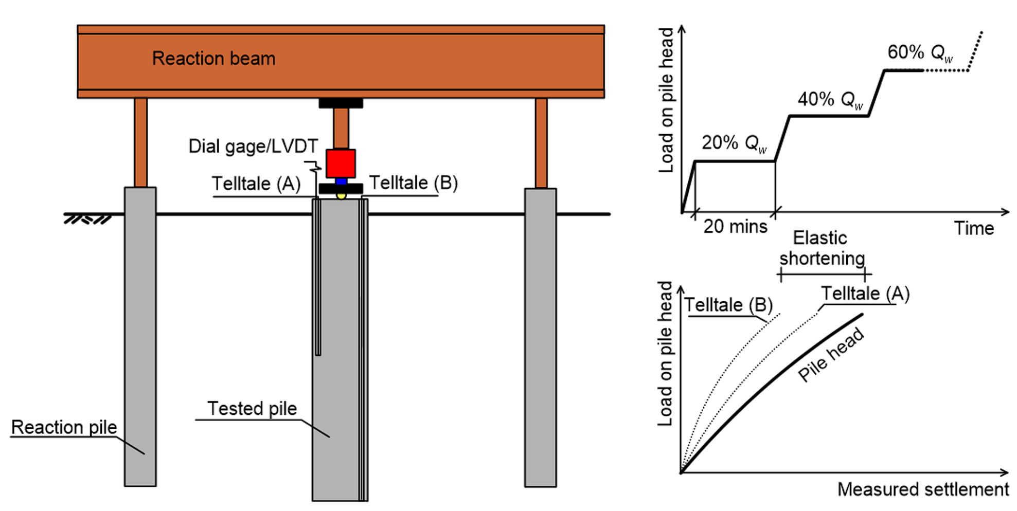
During a pile load test, the pile head is loaded according to a predetermined loading sequence described in relevant standards (Table 6.9) and the movement at the pile head (and perhaps at some points along the pile shaft, using strain gauges or metallic rods in tubes called telltales) is recorded (Figure 6.58).

| Load | Minimum load duration | |
|---|---|---|
| Stage S1 (proof and ultimate tests): Loading to serviceability load Qw | 20% Qw | 20 min |
| 40% Qw | 20 min | |
| 60% Qw | 20 min | |
| 80% Qw | 20 min | |
| 100% Qw | 4 hrs | |
| Stage S2 (proof and ultimate tests): Unloading from serviceability load Qw | 30% Qw | 10 min |
| 0% Qw | 20 min | |
| Stage G1 (proof and ultimate tests): Loading to estimated collapse load Qf | 30% Qf | 20 min |
| 40% Qf | 20 min | |
| 50% Qf | 20 min | |
| 60% Qf | 20 min | |
| 70% Qf | 20 min | |
| 80% Qf | 20 min | |
| 90% Qf | 20 min | |
| 100% Qf | 1 hr | |
| Stage U1 (ultimate tests only): Loading to in situ collapse load Qf,test | 110% Qf | 20 min |
| Further increments of 10% Qf | 20 min each increment | |
| Qf,test or maximum available test load | Hold only if Qf,test exceeds the maximum available test load | |
| Stage U2 (ultimate tests only): Unloading from in situ collapse load Qf,test | 0 | 10 min |
| Stage G2 (proof and ultimate tests): Unloading from estimated collapse load Qf | Loading decrements of 20% Qf | 10 min each decrement |
| 100% Qf | 10 min | |
| 80% Qf | 10 min | |
| 60% Qf | 10 min | |
| 40% Qf | 10 min | |
| 20% Qf | 10 min |
The load-settlement curve (or compliance curve) is plotted, and the collapse load and/or corresponding settlements at different test stages are determined by properly interpreting the results.
A pile load test is performed:
- To minimise risks by confirming the suitability of deep foundations to support the design action load without exceeding the allowable settlement, especially in projects of high geotechnical risk.
- To optimise design and construction procedures during the early stages of a project.
- To satisfy regulatory agency requirements.
Although static pile load tests are costly and time consuming, they may ultimately result in significant savings, as “in depth” project-specific knowledge of the behaviour of the pile-soil system may lead to reduction of necessary pile lengths, and to the adoption of a higher geotechnical reduction factor φg. Dynamic pile load tests are faster but, in the author’s view, more cumbersome to interpret and are not covered in this Part.
6.16.2 Description of test procedures
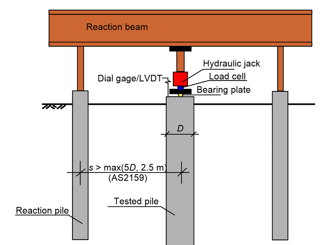
The axial load is applied on the pile by stacking sandbags or, more usually these days, by jacking against a reaction beam and reaction piles (Figure 6.59). Instead of reaction piles, anchors or a weighted platform may be used. Working piles may be used as reaction piles to carry the tension load, provided that:
- As illustrated in Figure 6.59, the centre-to-centre spacing between the reaction piles and the loaded pile will not be less than the greater of 5 times the test pile diameter, and 2.5 m (AS2159).
- Measures are implemented to ensure that any permanent displacement of the reaction piles will not affect their load carrying performance in serviceability and ultimate limit state conditions.
Calibrated load cells are used to measure the applied load, while the jack load should also be recorded from a pressure gauge. A spherical bearing plate is placed between the hydraulic jack and the reaction beam, to minimise eccentricities. The pile displacement and any rotation or tilt of the pile head are monitored either by a survey leveling system, or by 3 or more dial gauges or position sensors (LVDT’s) in conjunction with a reference frame, that is independent of the reaction system and the test pile. Often, the leveling system is used as back-up of dial gauges or LVDT’s.
Dial gauges or LVDT’s should preferably have a minimum of 75 mm of travel and a precision of 0.025 mm (less than 0.1% of the pile diameter and 0.1 mm, according to AS2159).

6.16.3 Proof and ultimate static load tests
Based on the objectives of the load test, pile load tests are classified into:
- Proof tests, where we seek to measure the settlement of the pile head under the serviceability load Qw, and confirm that the pile is able to carry a vertical load equal to the estimated (by means of the methods described earlier in this Part) collapse load Qf without developing excessive pile head settlement.
- Ultimate tests, where we seek to find the ultimate geotechnical strength (collapse load) Qf,test of the pile in situ.
As it is perhaps clear from the above, proof tests can be performed on working piles too, while ultimate tests are performed on sacrificial piles that are loaded up to failure.
When negative skin friction is not expected, the following maximum test loads Qmax are applied on the pile’s head (Figure 6.60):
For a proof load test to measure the settlement under serviceability conditions:
Qmax = Qw where Qw is the design serviceability load
For proof load test to verify the design geotechnical strength:
Qmax = Qf = S*/φg, where S* is the design action compressive load, or
Qmax = Qf,t = 1.2St*, where St* is the design action tensile load
For an ultimate load test:
Qmax = Qf,test or Qf,t,test which is the ultimate geotechnical strength (collapse load) of the pile as assessed in situ, from pile tests. This load must be estimated in advance, while sufficient allowance must be made in all aspects of the test setup, including the structural strength of the pile required to exceed this estimate.

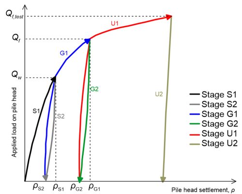
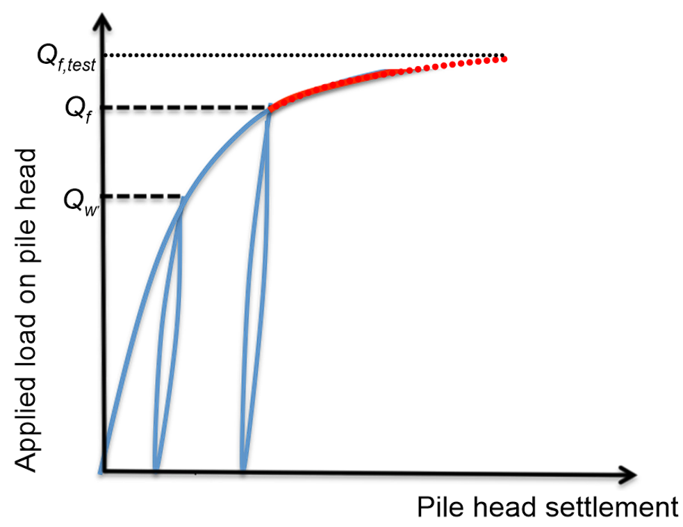
The load on the pile head must be applied in specific increments, according to the test procedure (Figure 6.61 and Table 6.9). Following application of each load increment, the load shall be sustained at a constant magnitude until the rate of pile head settlement is less than 0.5 mm per 15 min, commencing 5 min after applying any load increase. The minimum holding time specified in AS2159 is listed in Table 6.9. Both pile loading and unloading must comply with the minimum load duration.
Successful proof tests must satisfy certain acceptance criteria related to the pile head settlement at the end of the loading and unloading stages S1-S2 and G1-G2 (Table 6.10). If these criteria are not met, the design bearing capacity must be reassessed.
Various methods have been proposed for the definition of the in situ collapse load from ultimate tests Qf,test as it is rarely explicitly identifiable from the load-displacement curve: It has been mentioned earlier that piles rarely develop a “brittle” plunging failure mode, and usually harden until unacceptable settlements develops (see Chapter 6.7). According to AS2159, the in situ ultimate geotechnical strength Qf,test of the pile is the greater of:
- The maximum pile load which can be sustained for a period of 10 min, and
- The pile load corresponding to the maximum settlement that would cause failure of the structure (not the maximum allowable settlement of the structure, which corresponds to serviceability conditions).
In the absence of project-specific values of the maximum allowable settlement, this shall be considered to be equal to 0.05D for driven piles and 0.1D for drilled shafts.
| Stage | Load at the end of stage | Pile head settlement at the end of stage (mm) |
|---|---|---|
| S1 | Qw |  |
| S2 | 0 |  |
| G1 | Qf |  |
| G2 | 0 |  |
| D is the pile diameter; L is the pile length; Ap is the area of the pile’s section; Ep is the Young’s modulus of the pile’s material | ||
Alternatively, one case use the “offset limit” method proposed by Davisson (1972) (FHWA 2006). As illustrated in Figure 6.62a, the elastic shortening of the pile head under the in situ collapse load Qf,test is estimated as:
(6.79) 
For piles with diameter D < 0.60 m the failure load is the one that results in a pile toe settlement equal to:
(6.80) 
For piles with diameter D > 0.60 m the failure load is the one that results in a pile toe settlement equal to:
(6.81) 
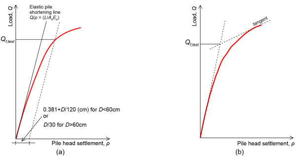
For drilled shafts, the graphical double tangent method can be used (Figure 6.62b) to determine Qf,test. The load-displacement curve is plotted, and the in situ collapse load Qf,test is defined at the intersection of the tangent lines of the initial and final part of the curve. When applying this method one should bare in mind that the elastic shortening of the pile (Qf,testL/EpAp) is not considered. Thus, the in situ collapse load of short piles may be over-estimated, and the in situ collapse load of long piles may be under-estimated, if the elastic shortening of the pile (Eq. 6.79) is significant.
6.16.4 Geotechnical strength reduction factor φg according to AS2159 accounting for pile load test results.
As discussed earlier, when static pile load tests are performed to verify in situ the design assumptions, AS2159 allows for the adoption of a higher value for the geotechnical strength reduction factor φg. The basic geotechnical strength reduction factor φgb derived via the risk assessment procedure described in Chapter 6.8, is increased as:
(6.82) 
where φtf = 0.9 for static load tests, and
(6.83) 
with p (%) being the percentage of total piles tested that meet the acceptance criteria listed in Table 6.10. When a systematic pile load testing campaign is performed, the above procedure will lead to substantial increase of the strength reduction factor: For example, if proof load tests are performed in 1 every 20 working piles (p = 5%), and all piles meet the acceptance criteria, the geotechnical strength reduction factor can be increased from e.g. φgb=0.56 to
(6.84) 
