6.14 Ultimate geotechnical strength of drilled shafts subjected to axial compressive loads
The general concept for estimating the collapse load of driven piles under drained and undrained loading conditions using analytical formulas (α– and β-Method) can be applied for the estimation of the collapse compressive load of drilled shafts too. However, the factors employed in the calculation of the skin friction resistance and the end bearing resistance with the α-Method and the β-Method may have to be modified, to account for the soil disturbance during excavation of drilled shafts.
6.14.1 Estimating the ultimate geotechnical strength of drilled shafts with the α-Method
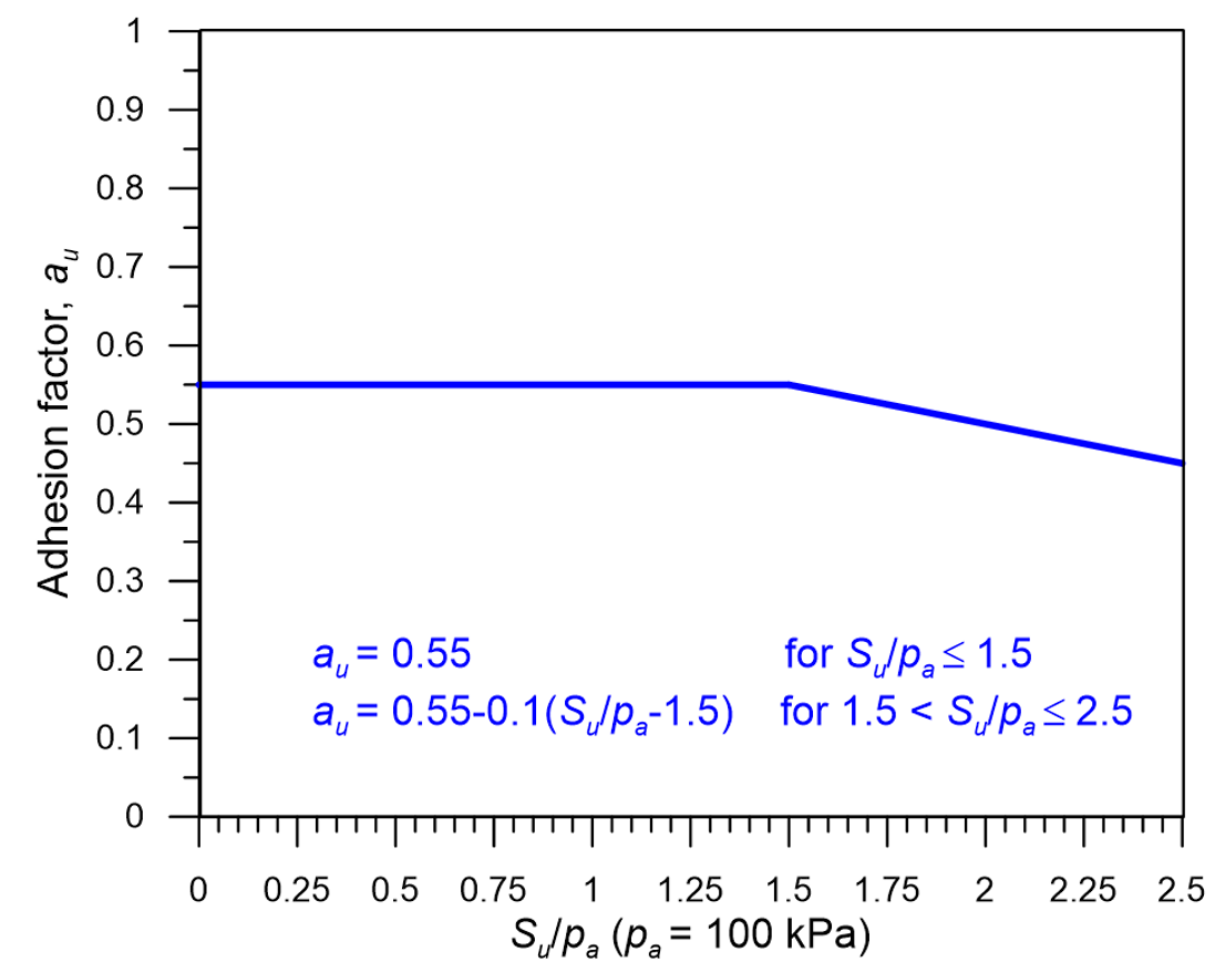
For the estimation of the adhesion factor au for drilled shafts, the formula proposed by O’Neil and Reese (1999) and depicted in Figure 6.41 should be used for drilled shafts. Observe that it provides significantly more conservative values compared to the corresponding Figure 6.18 for driven piles.
In addition, the bearing capacity factor Νcp employed in the estimation of the end-bearing resistance under undrained loading conditions with Eq. 6.9 is replaced by the factor Ν*cp:
(6.68) ![N_{cp}^ * = 1.33\left[ {\ln \left( {{I_r}} \right) + 1} \right]](https://oercollective.caul.edu.au/app/uploads/quicklatex/quicklatex.com-d44a08c0022d0b9fb4340aa8b487d296_l3.png "Rendered by QuickLaTeX.com")
where Ir is the rigidity index of the soil, equal to Ir = G/Su = Eu/3Su. When undrained triaxial tests are not available for the estimation of the shear G or of the undrained Young modulus of the soil Eu, one may obtain the values from Table 6.8, using linear interpolation for intermediate values.
![Chart providing the variation of the adhesion factor au with the dimensionless undrained strength Su/pa. The plotted line is described with the following function: au = 0.55 for Su/pa <1.5, au = 0.55-0.1[(Su/pa)-1.5] for 1.5<Su/pa<2.5](https://oercollective.caul.edu.au/app/uploads/sites/143/2025/03/6.41-hr-e1743553282440.png)
| Undrained shear strength, Su (kPa) | Ir | N*cp |
|---|---|---|
| 25 | 50 | 6.53 |
| 50 | 150 | 7.99 |
| 100 | 250 | 8.67 |
| 200 | 300 | 8.91 |
6.14.2 Estimating the ultimate geotechnical strength of drilled shafts with the β-Method
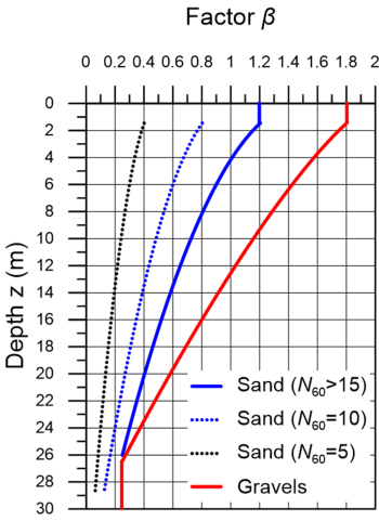
Generally, the formulas for driven piles can be applied as-is for drilled shafts too. Reese et al. (2006) proposed specific formulas for estimating the skin friction resistance and end-bearing resistance of drilled shafts installed in coarse-grained soils on the basis of SPT test data. More specifically, the factor β for medium-to-dense sands with uncorrected SPT blow count Ν60 > 15 can be estimated as (Figure 6.42):
(6.69) 
while for loose-to-medium sands with uncorrected SPT blow count Ν60 < 15:
(6.70) ![\beta = \dfrac{{{N_{60}}}}{{15}}\left[ {1.5 - 0.245\sqrt z } \right]](https://oercollective.caul.edu.au/app/uploads/quicklatex/quicklatex.com-e7e63d4c5f01fbc7ceea0a7436d10851_l3.png "Rendered by QuickLaTeX.com")
and for gravels:
(6.71) 
where z is the depth measured from the ground surface. The skin friction resistance estimated with this method must be limited to fsf = βσ′z0 < 200 kPa, arguably a quite high value if we consider Table 6.4 and the fact that construction of drilled shafts will result in release of stresses in sand. The author would recommend considering a more conservative cap on the skin friction resistance calculated with the above formulas, in line with Table 6.4.
As far as the end-bearing resistance qbf is concerned, Reese et al. (2006) recommend the following formula:
(6.72a) 
(6.72b) 
It is reminded that the end-bearing resistance (units: force) of closed-end piles of diameter D is calculated from the end-bearing resistance (units: stress) as:
(6.73) 
