6.7 Piles subjected to axial compressive loads – general concepts
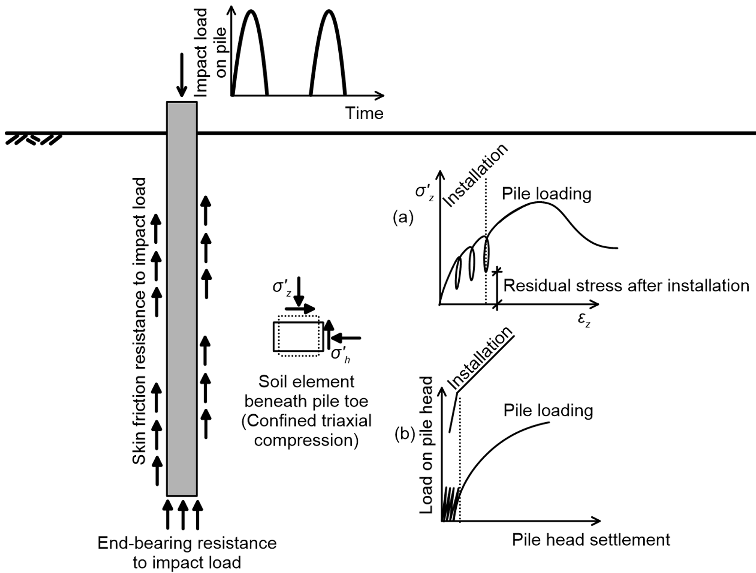
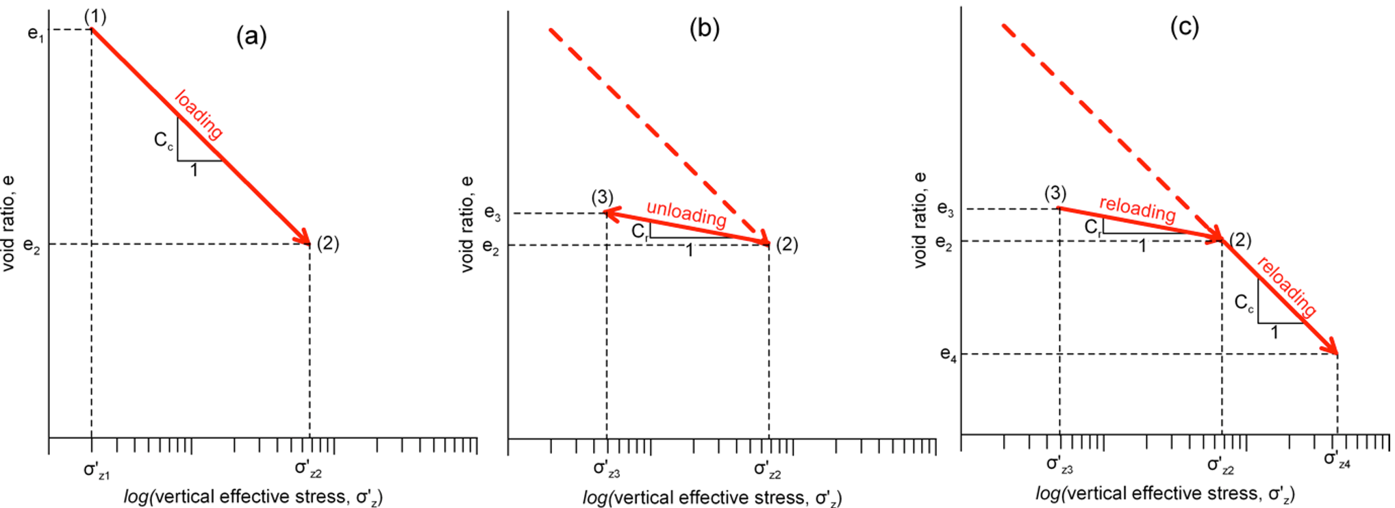
After installation, the vertical load applied on the pile is transferred to the surrounding soil via skin friction and end-bearing mechanisms. The stress-strain response of a soil element below the pile toe will initially follow the loading curve (Figure 6.15a), which is analogous to the reloading curve of an over-consolidated soil from the oedometer test (see Figure 4.28). Note however that, unlike the oedometer test, the loading curve will not “exactly” match the installation curve, as installation loads are dynamic.
As we increase the vertical load applied on the pile head, a failure surface will gradually develop. Two possible pile failure mechanisms are presented in Figure 6.16a, assuming soil is rigid plastic material. These idealised failure mechanisms, which may develop when numerically simulating vertical loading of piles considering an elastic-rigid plastic material for the soil (Figure 6.16b), do not take into account neither the disturbance of soil around the shaft, nor the confined soil conditions below the pile toe. So actually they will not develop fully in practice, expect maybe in the case of a very short pile.
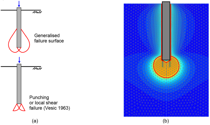
In order for the full skin friction resistance to be mobilised, a vertical pile displacement of 2.5 mm to 10 mm is required. On the contrary, the full end-bearing resistance is mobilised at a much higher vertical displacement, between 10% and up to 30% of the pile diameter. This means that the full skin friction resistance will develop first, for a load lower than the collapse load, followed by the end-bearing resistance.
In practice, we can assume that the full end-bearing resistance develops when a failure mechanism similar to that of shallow foundations is formed below the pile toe, and calculate the pile resistance by following the same concepts as for an embedded shallow footing. Due to the high degree of confinement under the toe, even over-consolidated clays or very dense sands will not exhibit a peak in their stress-strain response (“collapse load”) but will rather strain harden until intolerable settlements develop (“failure load”).
Following the nomenclature introduced in Part 5, we will use the term “collapse load Qf” to refer to the ultimate geotechnical strength of piles (bearing capacity) in terms of force. The design capacity of piles is introduced in the next chapter.
