6.6 Pile driving effects
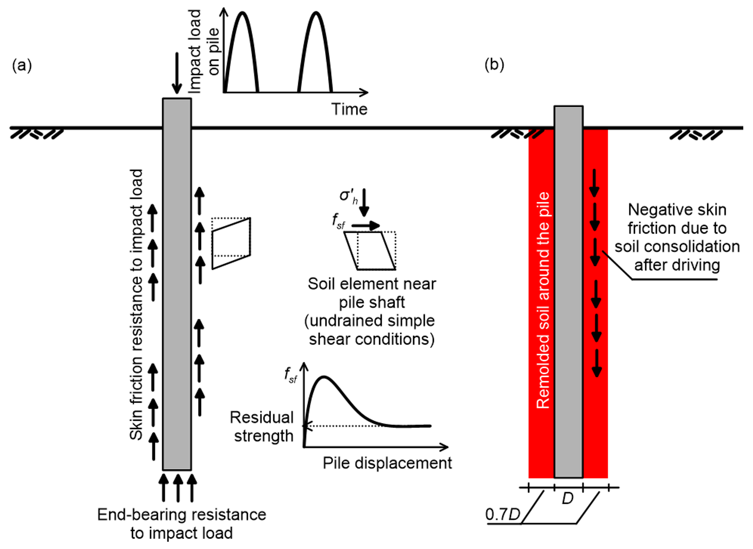
Pile driving imposes an impact load, and each hammer blow results in a stress wave that propagates through the pile, and into the soil. The resistance during driving (which can be measured during installation by recording the advancement of the pile head per hammer blow) can be used to infer the pile’s collapse load, as discussed in later sections. The impact load is dynamic, thus excess pore water pressures will develop during pile driving in fine-grained soils, and soil deformation will take place under undrained conditions, without volume change (Figure 6.14a).
Pile driving is an imposed displacement problem: The soil adjacent to the pile shaft is subjected to radial compressive strains and shear strains, as it deforms to accommodate pile penetration, resulting in a stress state that is similar to undrained simple shear conditions. Thus, stresses in soil will depend on the properties of the variable soil layers, if the profile is not homogeneous. Note that pile installation will result in large soil strains, thus the ultimate soil resistance to pile driving will be associated with the residual shear strength of sensitive soils, rather than their peak strength.
Equilibrium of mass suggests that the volume of the soil displaced and remolded is equal to the volume of the pile, for closed-end piles. A zone of minimum radius of about 0.7D, where D is the diameter of the pile, will be affected and soil in this zone will generally be less stiff than the original soil (Figure 6.14b).
After installation, excess pore pressures that (may) have developed in the disturbed zone due to the application of the additional stresses will begin to dissipate, and the soil will reconsolidate. During reconsolidation, two phenomena take place: a) as the volume of the soil decreases, negative skin friction will develop along the soil-pile interface, reducing its load capacity b) the effective stresses increase as pore pressures dissipate, increasing soil strength, and thus the pile’s skin friction resistance. Given the fact that the effect of these two phenomena is antagonistic, we tend to ignore them when using simplified formulas for pile design.

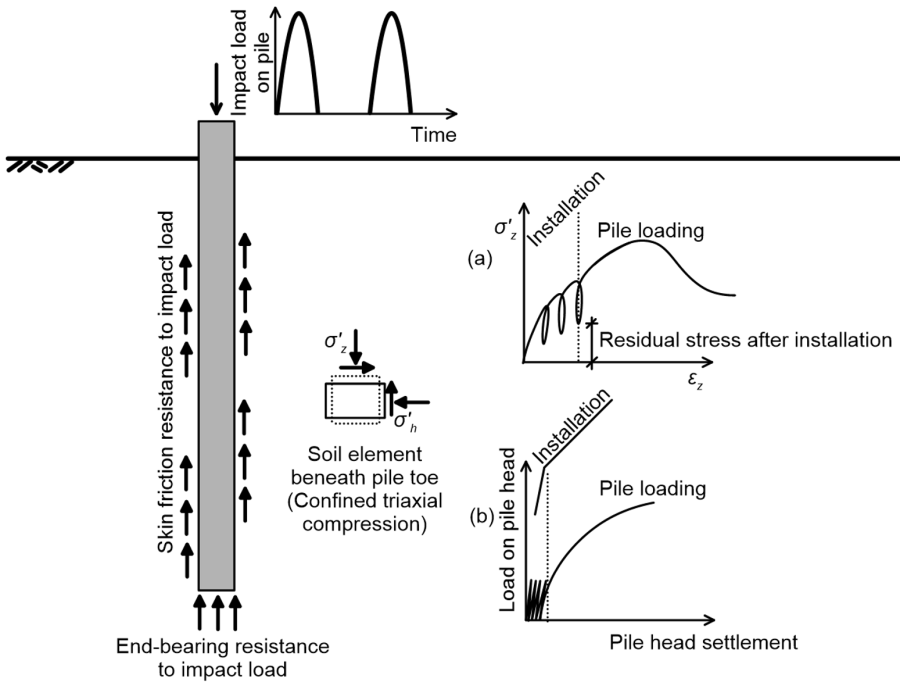
Let’s consider now a soil element below the pile toe (Figure 6.15a). During driving, this element will undergo a vertical compressive stress due to the axial load from the pile, and a shear stress, due to the difference between vertical and lateral stresses. Unlike soil elements along the pile shaft, a soil element below the pile’s toe is severely confined laterally and vertically. If the pile is not pushed continuously into the soil, and installation involves impact loading-unloading-reloading, the stress-strain curve of the soil element will not be monotonic, as illustrated in Figure 6.15a.
As the soil below the pile toe is constrained vertically, due to the overburden pressure, but also radially, due to the lateral restrain imposed by the nearby soil, it undergoes a constrained mode of deformation. Consequently, after installation some residual stress will remain, despite a vertical load not being applied on the pile (Figure 6.15b), and the soil below the pile will not be in its original, geostatic stress state. This residual stress results from the restriction imposed on the soil by the weight of the pile and the negative skin friction acting at along the shaft, and is analogous to a preconsolidation stress. In other words, installation of the pile applies an apparent preconsolidation stress to the soil below the toe, which however cannot be straightforwardly determined.
If observations/measurements obtained during pile driving are used to indirectly estimate its collapse load, though pile driving formulas discussed in Chapter 6.17, one should bear in mind that the excess pore water pressures developing below the pile toe will result in additional resistance of piles penetrating into fine grained saturated soils, which may lead to over-estimating the long-term pile capacity. When installation stops, these excess pore pressures will gradually dissipate, leading to (some) pile settlement. However, if the pile toe is embedded into a highly overconsolidated clay or dense sand, negative excess pore pressures may develop due to their dilative response: Remember that dilating soils which are prone to volume contraction tend to draw in water to compensate volume changes, resulting in negative pore pressure development under undrained loading conditions. This will lead to a temporary increase in effective stresses and a (temporary) increase in the soil strength.
