6.2 Common pile types
Two main categories of piles can be identified, depending on their construction method:
- Displacement, or driven piles (Figure 6.6) displace and compact the ground through which they are installed, by nailing or screwing. Displacement piles may be installed by hammering, pushing, screwing etc.
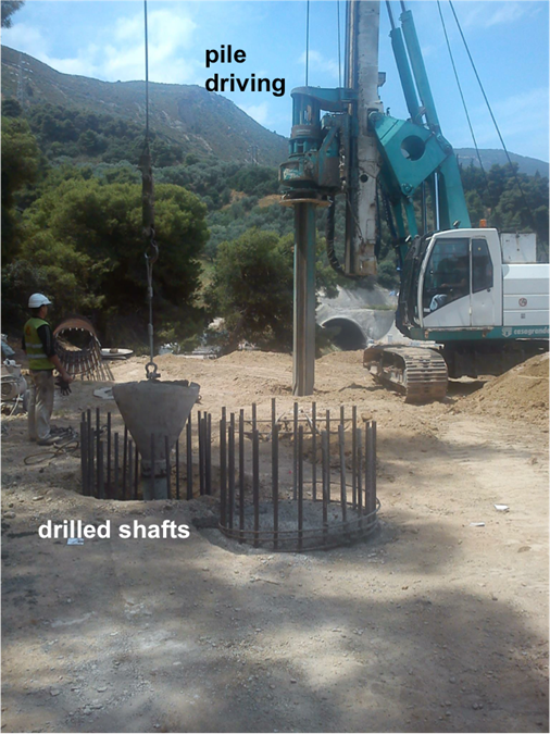
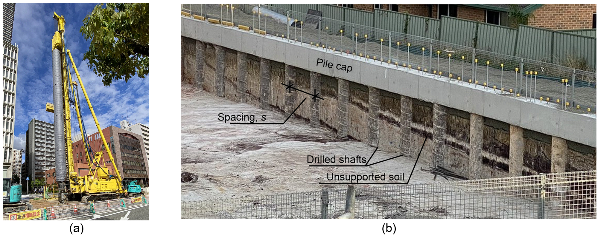
- Non-displacement piles, or drilled shafts, or bored piles or drilled piers (Figures 6.6 and 6.7) are constructed by drilling and removing soil to form a cylindrical shaft into the ground (Figure 6.7). Subsequently a rebar cage is installed, and the void is filled with concrete. The sides of the excavated void may or may not be supported.
In this Part we will use the term piles to refer to driven piles and the term drilled shafts to refer mainly to non-displacement concrete piles that are cast in situ.
Furthermore, depending on the pile fabrication and installation method, displacement (driven) piles are subdivided in:
- Preformed piles: Steel (hollow or solid section), timber, reinforced or pre-stressed concrete sections, that are installed into the ground and left in position.
- Driven cast in place piles: Formed in situ by driving a tubular liner to form a void in the ground, which is then filled with concrete. The liner may be permanent or temporary.
- Screwed cast in place piles: Formed in situ by screwing a threaded tube into the ground, with concrete poured as the screw head is withdrawn.

Depending on the pile installation method, non-displacement piles (drilled shafts) are subdivided into:
- Supported drilled shafts; when the excavated shaft is supported permanently (e.g. using steel liner) or temporary (e.g. using retractable liner or slurry)
- Unsupported drilled shafts; when the excavated void is not supported
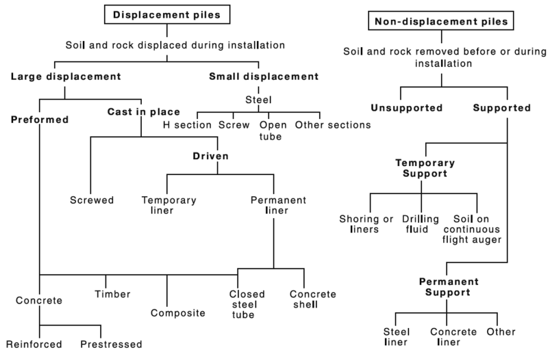
A detailed classification of pile types according to AS2159 is presented in Figure 6.8.
Selection of the appropriate pile type for a specific project depends on the geotechnical and hydrogeological conditions of the site, environmental restrictions, durability requirements as well as of course the available equipment and experience. For example, in loose sands driven piles are preferred, as drilled shafts will require some form of casing or slurry to support the walls of the shaft from caving in. A tapered pile section will develop the maximum skin friction when driven through loose sands. On the contrary, in a deep soft clay layer, a rough concrete pile will feature increased skin friction resistance and allow for faster dissipation of excess pore pressure that will develop during construction. Or, when the geotechnical investigation reveals the existence of boulders above the bearing stratum, a large diameter drilled shaft may be preferable, depending on the size of boulders.
