5.5 Bearing capacity of footings on layered soils
5.5.1 Critical thickness of the surficial soil layer
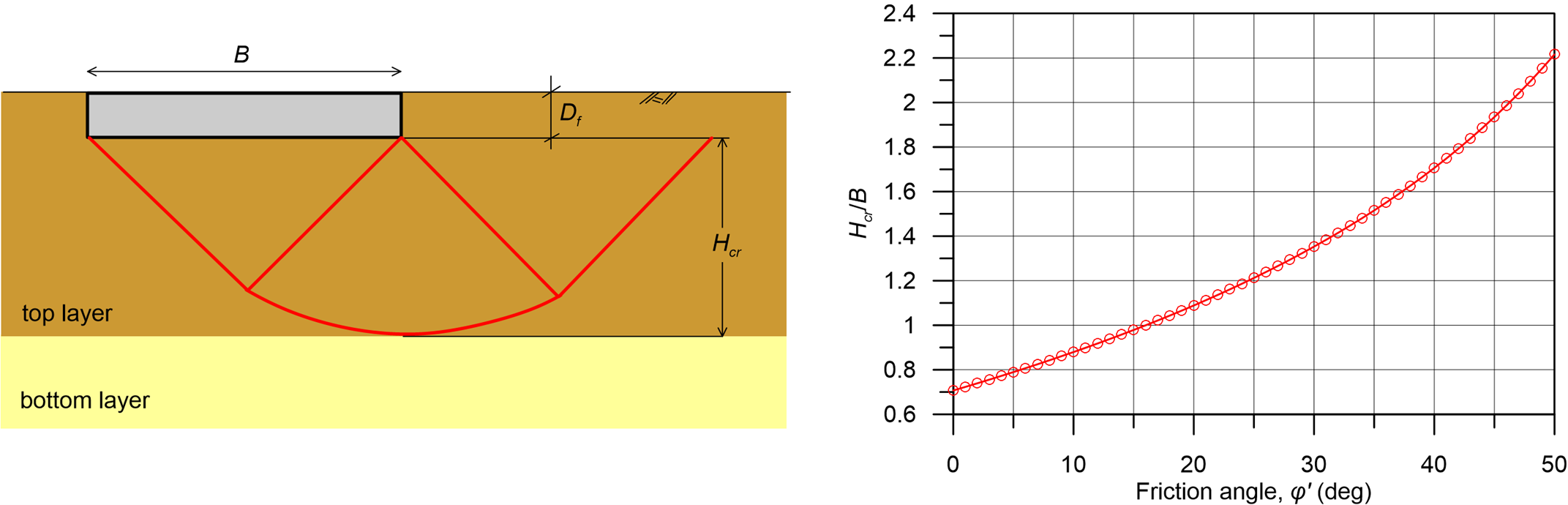
One of the key assumptions of the common analytical solutions presented in Chapter 5.4 is that of uniform soil conditions, which is rarely the case in practice. When the geotechnical investigation reveals a non-uniform soil profile, we have to estimate whether the thickness of the top soil layer, measured below the embedment depth, is enough so that the failure surface will develop entirely inside it (Figure 5.36).
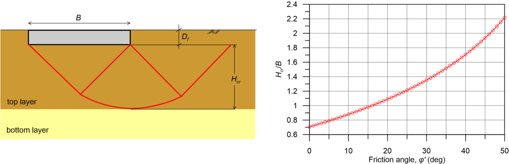
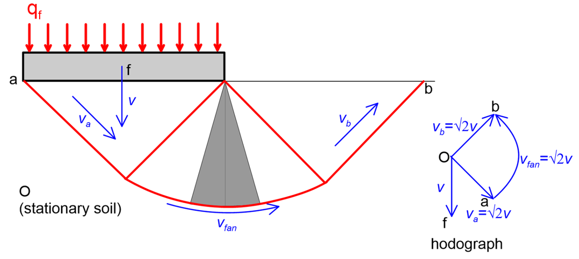
It is reasonable to assume that if the thickness of the soil layer below the foundation, Hcr is less than the depth that the Prandtl mechanism penetrates into the soil (Figure 5.26) the failure surface will be entirely contained in the top soil layer, and the subsoil can be considered as homogeneous for bearing capacity calculations.
(5.35) 
Where A = (45°+φ′/2) in rad.
Alternatively, the critical thickness Hcr can be calculated as (Budhu 2011):
(5.36) 
where:
- qtop is the bearing capacity of the footing with the particular dimensions, resting on the surface of an infinitely deep layer with the properties of the top soil layer, and
- qbottom is the bearing capacity of the footing with the particular dimensions, resting on the surface of an infinitely deep layer with the properties of the bottom soil layer.
If the thickness of the top soil layer measured below the embedment depth, Htop is less than the critical thickness, Hcr, there is no general analytical method to estimate the bearing capacity, except of course numerical methods. Some characteristic cases are examined in the following paragraphs.
5.5.2 Footing on a soft clay layer overlying a stiff soil formation
In the case where a thin soft clay formation is found near the ground surface, good engineering practice suggests excavating the soft clay layer, and replacing it with well-compacted coarse-grained fill material. Founding structures directly on soft clays with shallow foundation should be avoided, except light structures such as one-storey buildings.
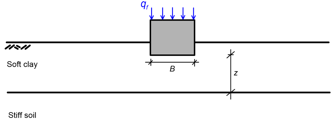
Experimental results have shown that in the case of a footing resting on soft clay overlying a stiffer stratum, the mechanism of bearing capacity consists of lateral squeezing of the soft soil, as the footing “sinks” into the top layer. Tomlinson and Boorman (1995) proposed the following expressions to estimate bearing capacity in that case:
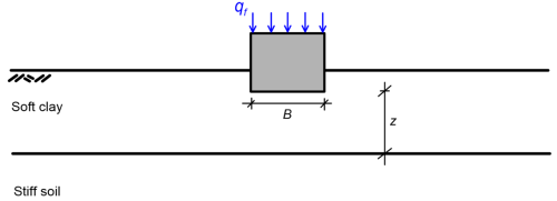
For circular/square footings:
(5.37) 
For strip footings:
(5.38) 
where z is defined in Figure 5.37 above. When B/z < 2 for circular/strip footings or B/z < 6 for strip footings (Figure 5.37), the expressions for homogeneous soil should be rather used.
5.5.3 Footing on stiff soil overlying a soft clay layer
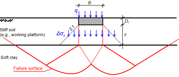
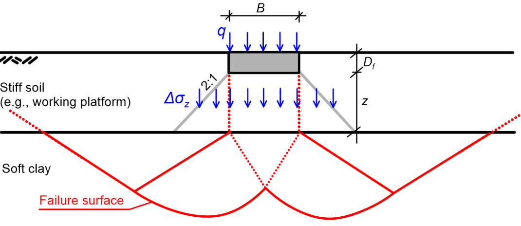
This case could well correspond to the common problem of a footing resting on a foundation improvement layer made of well-compacted coarse-grained fill, overlying a soft subgrade. A “punching” failure mechanism may develop under these circumstances (Figure 5.38a).
A simplified method for estimating the bearing capacity of a footing of any shape resting on the surface of, or embedded in a stiff soil formation overlying a soft clay layer consists of the following steps: First, we estimate the bearing capacity of the footing while considering uniform soil with the properties of the top stiff soil layer, which must not be critical for the design.
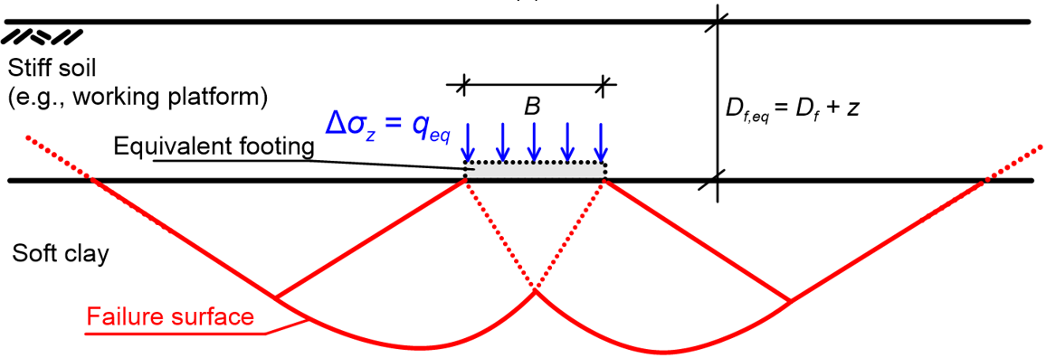
Accordingly, we estimate using Eq. 5.24 the net bearing capacity qeq of a hypothetical equivalent footing with the same shape and dimensions, embedded at a depth Df,eq = Df+z equal to the thickness of the top stiff soil layer (Figure 5.38). Bearing capacity failure of the actual footing will be reached when the vertical stress Δσz transferred from the actual footing to the interface of the stiff soil-soft clay layer (Figure 5.38b) becomes equal to qeq i.e., Δσz = qeq. The following approximate expressions can be used to calculate Δσz, while assuming 2:1 stress distribution (see Chapter 3.6):
For a rectangular footing:
(5.39) ![\Delta {\sigma _z} = q\left[ {\dfrac{{BL}}{{\left( {B + z} \right)\left( {L + z} \right)}}} \right]](https://oercollective.caul.edu.au/app/uploads/quicklatex/quicklatex.com-09489809add8dd1f45f40b8c6fb51c3b_l3.png "Rendered by QuickLaTeX.com")
For a square/circular footing:
(5.40) ![\Delta {\sigma _z} = q{\left[ {\dfrac{B}{{\left( {B + z} \right)}}} \right]^2}](https://oercollective.caul.edu.au/app/uploads/quicklatex/quicklatex.com-17c5b95325834489ed13f34f4ad2b873_l3.png "Rendered by QuickLaTeX.com")
For a strip footing:
(5.41) ![\Delta {\sigma _z} = q\left[ {\dfrac{B}{{\left( {B + z} \right)}}} \right]](https://oercollective.caul.edu.au/app/uploads/quicklatex/quicklatex.com-32366eadcc74ce23adf029b405aa48fc_l3.png "Rendered by QuickLaTeX.com")
in the above expressions q is the net bearing capacity of the actual footing. Therefore substituting Δσz = qeq in the Eqs. 5.39 to 5.41 that corresponds to the actual footing shape will provide its net bearing capacity q. If the actual footing is embedded in soil, its bearing capacity will be qf = q + γDf.

Note that the methodology described above conservatively ignores the shear resistance of the top layer, and the energy dissipated along the shear planes located with it. Another simplifying assumption is that the inclination of the shear planes relative to the vertical in the top layer is ignored i.e., the width of the equivalent, hypothetical footing is taken equal to the width of the real one. There are more refined methods in the literature that do not require introducing these assumptions, however their range of application is limited to specific footing geometries and soil types. Such a method has been developed by Salimi Eshkevari et al. (2019a) for estimating the bearing capacity of strip footings resting on the surface of a sand layer overlying a soft clay, which is relevant to the design of working platforms for tracked plants. Salimi Eshkevari et al. analysed the results of a series of Finite Element Limit Analyses and concluded to the following expression that provides the bearing capacity of a strip footing on a layered profile of sand over clay qf,l:
(5.42) ![{q_{f,l}}B = \gamma {H^2}{K_{sr}}\tan \varphi ' + {N_{cu}}{S_u}\left[ {B + 2H\tan \theta } \right] + \gamma {H^2}\tan \theta \le qB](https://oercollective.caul.edu.au/app/uploads/quicklatex/quicklatex.com-ca2fd53f32add04e093edddb4a390799_l3.png "Rendered by QuickLaTeX.com")
where B is the footing width, H is the thickness of the sand layer, γ is the unit weight of sand, φ′ is the friction angle of sand, Su is the undrained shear strength of the clay layer, Ncu = 5.14 is the bearing capacity factor for strip footings on undrained soil, q is the bearing capacity of a footing of width B resting on the surface of uniform sand, calculated according to Eq. 5.25. The angle θ that provides the inclination of the shear planes that will develop in the sand layer can be calculated as:
(5.43) 
(5.44) 
(5.45) 
Note that angle θ can be positive or negative. Thus, unlike the approximate method described above, the width B+2Htanθ of the equivalent footing in Figure 5.38 can be greater, or less than the width of the actual footing B. Finally, the punching shear coefficient Ksr, that is correlated with the normal stress acting on the shear planes that will develop in the sand layer, is calculated as:
(5.46) 
(5.47) 
5.5.4 Strip footings on layered sands
Estimation of the bearing capacity of strip footings resting on the surface of a relatively thin layer of dense sand overlaying a weak layer of loose sand underpins the design of working platforms for heavily loaded tracked piling rigs and cranes, on sites which loose sand deposits are found at the ground surface. Hanna (1981) was among the first to study this problem, and concluded to the following expression for estimating the bearing capacity in terms of stress when a punching failure mechanism develops:
(5.48) 
where B is the footing width, H is the thickness of the top (dense) sand layer, γ1 is the unit weight of the dense sand layer, φ′1 is the friction angle of the dense sand layer, qb is the bearing capacity of a footing of width B embedded at depth H in a uniform sand layer with the properties of the loose sand, calculated as:
(5.49) 
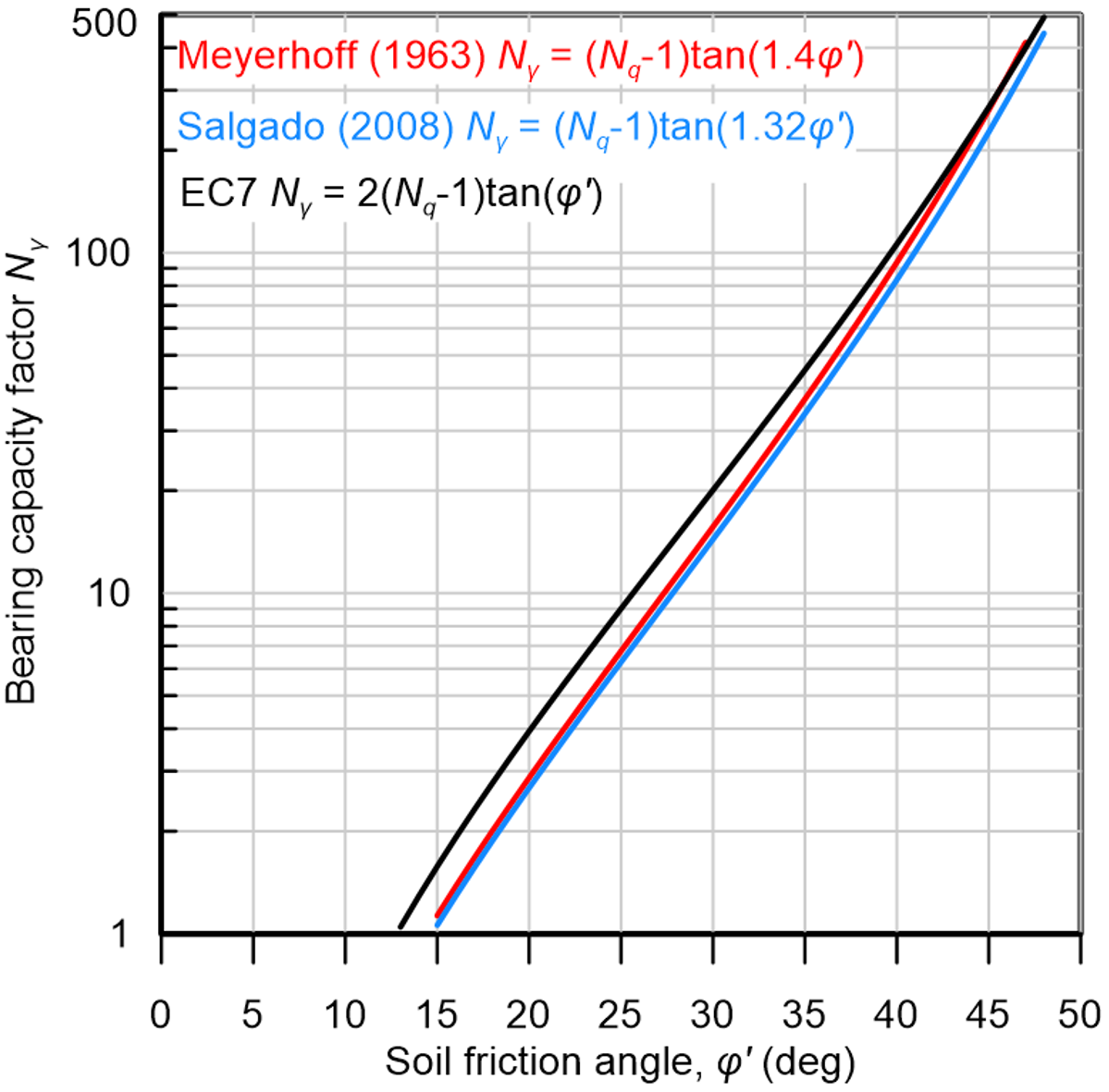
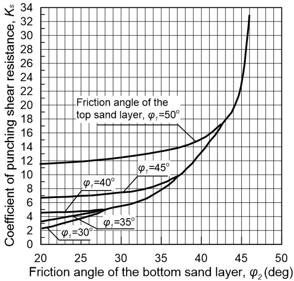
where γ2 is the unit weight of the loose sand layer, while Νγ2 and Νq2 are the bearing capacity factors of the loose sand layer, featuring friction angle φ′2, calculated according to Eq. 5.18 and Figure 5.31, respectively. Moreover, q in Eq. 5.48 is the bearing capacity of a footing of width B resting on the surface of uniform dense sand with friction angle φ′1 , calculated according to Eq. 5.25, and Ks is a punching shear resistance coefficient that depends on the friction angles of the two sand layers, and is provided in Figure 5.39.

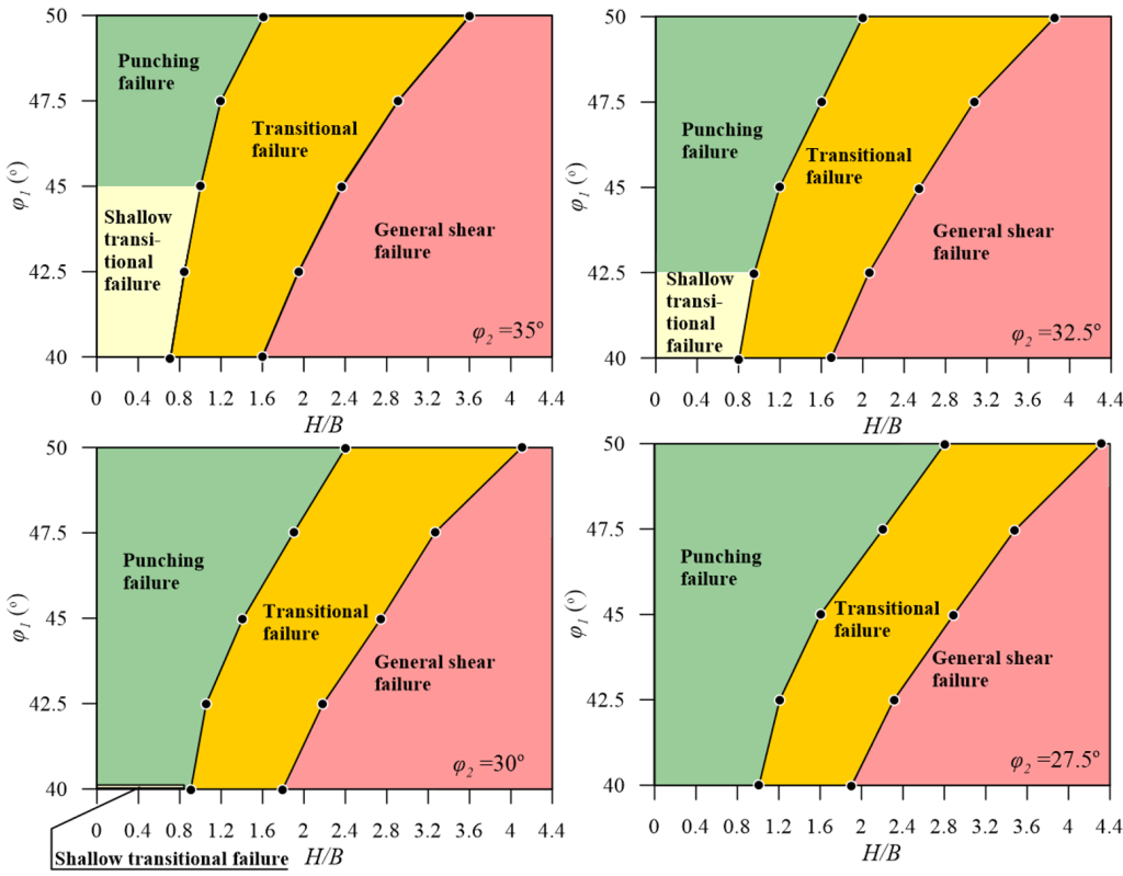
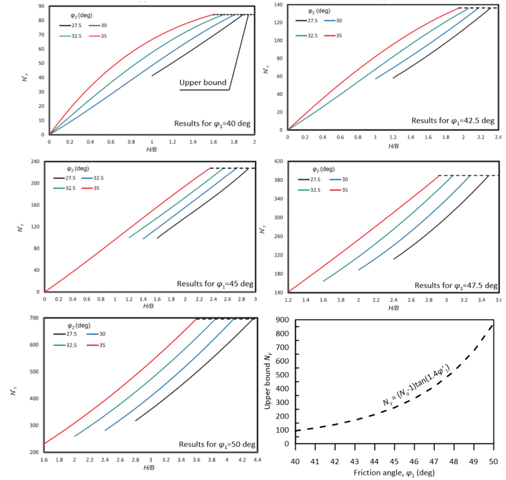
An important assumption underlying Hanna’s Eq. 5.48 is that a punching failure mechanism develops, irrespective of the relative strength of the two layers. Salimi Eshkevari et al. (2019b) have shown that the failure mechanism that will develop depends on the friction angles of the two layers, as well as the ratio of the thickness of the top dense sand layer over the width of the footing H/B. Using Figure 5.40 one can determine which failure mechanism will develop. Accordingly, Salimi Eshkevari et al. (2019b) proposed the following expression for calculating the bearing capacity of a strip footing resting on dense sand over loose sand, for the cases where a transitional (or shallow transitional) mechanism is expected to develop:
(5.50) 
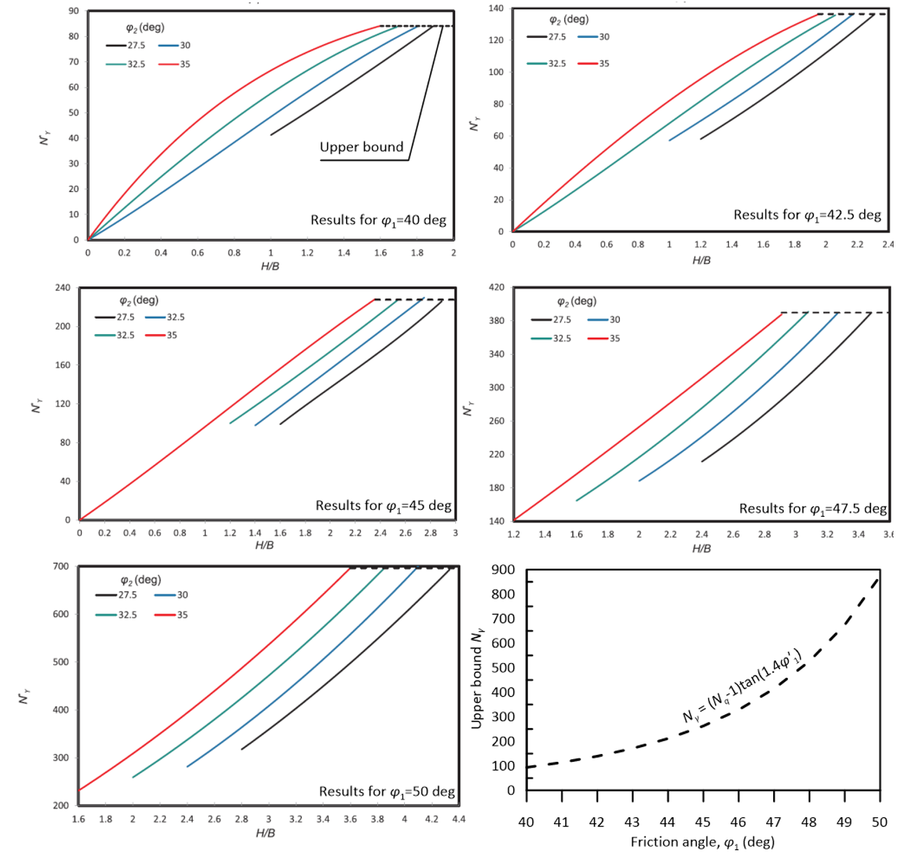
where the modified bearing capacity factor Nγ* is given in Figure 5.41 for different values of φ′1, φ′2 and H/B. If Figure 5.40 suggests that a punching failure mechanism will develop, Salimi Eshkevari et al. recommended using Hanna’s expression (Eq. 5.48) to determine the bearing capacity. Bearing capacity factor values in Figure 5.41 are applicable to the case where γ1/γ2 = 1.2, which is probably a reasonable approximation for most practical cases. Note also that Figure 5.41 covers only specific H/B ranges for which a transitional mechanism will develop. Finally, the upper bound to the bearing capacity factor Nγ* (dashed lines in Figure 5.41) is the conventional bearing capacity factor Νγ, and indicates cases where the thickness of the top dense sand layer exceeds the critical thickness, thus a general shear failure mechanism will develop and qf,l = q.
5.5.5 Footings on multi-layered soil profile
A lower-bound estimate of the bearing capacity of a footing resting on a multi-layered soil profile can be found by simply considering a homogeneous soil with the properties of the weakest layer, an approach that may lead to perhaps over-conservative results. Numerical methods are recommended for the treatment of such problems.
